
Method for performing milling microgroove machining by utilizing ultrafast laser

An ultrafast laser and milling technology, used in laser welding equipment, metal processing equipment, manufacturing tools, etc., can solve the problems of sacrificing groove depth and aspect ratio to increase thermal effects, and achieve the improvement of ablation threshold, reduction of width, calculation of small amount of effect

Active Publication Date: 2018-10-12
BEIJING SATELLITE MFG FACTORY
View PDF7 Cites 4 Cited by
  • Summary
  • Abstract
  • Description
  • Claims
  • Application Information

AI Technical Summary

Problems solved by technology

[0004] The technical problem to be solved by the present invention is: aiming at the deficiencies such as the depth and aspect ratio of the sacrificial grooves and the aggravated thermal effect existing in the ultrafast laser processing in the prior art, it provides a method of greatly reducing the microgrooves without significantly reducing the processing depth. Method of milling width

Method used


Image

  • Method for performing milling microgroove machining by utilizing ultrafast laser
  • Method for performing milling microgroove machining by utilizing ultrafast laser

Examples


Embodiment Construction

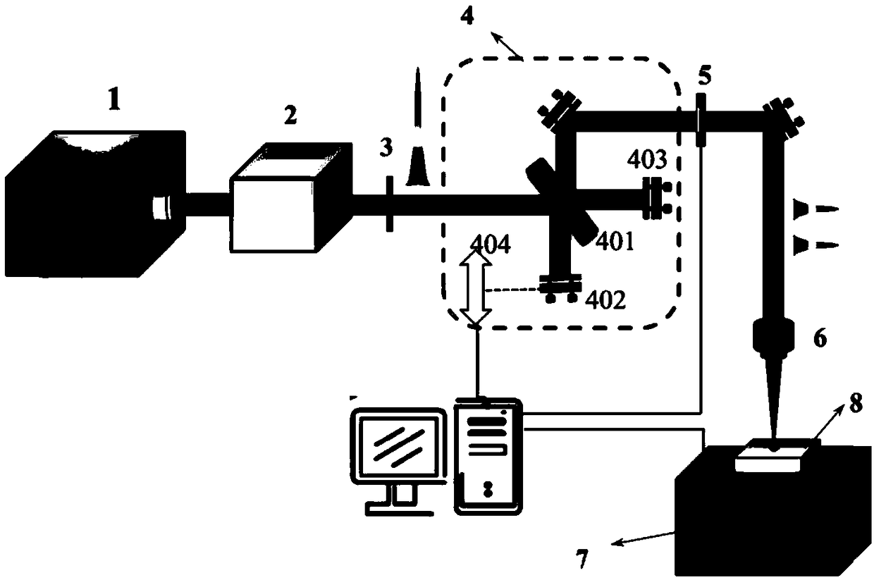
[0024] A method for milling microgrooves using ultrafast lasers, such as figure 2 As shown, by utilizing a laser milling slot comprising a laser 1, an optical parametric amplifier 2, an energy attenuation sheet 3, a Michelson interferometer 4, a linear translation stage 404, an optical shutter 5, a focusing lens 6, and a six-degree-of-freedom translation stage 7 The system performs laser groove cutting on the material 8 to be processed, and changes the single-pulse sequence laser to a double-pulse sequence laser to reduce the width of the milling groove and obtain an accurate value of the milling groove width through calculation, such as figure 1 As shown, the specific steps are as follows:

[0025] Step 1: Adjust the position and attitude of the internal components of the laser milling groove device, turn on the laser 1, measure the wavelength of the laser input laser according to the optical parameter amplifier 2, and convert the input wavelength λ1 of the input laser into ...


PUM


Abstract

Provided is a method for performing milling microgroove machining by utilizing ultrafast laser. By utilizing a laser milling groove system comprising a Michelson interferometer, single pulse sequencelaser is changed into double pulse sequence laser; by increasing an optical path difference of two interference arms of the Michelson interferometer, pulse delay of the double pulse sequence laser isindirectly increased; time delay of the laser is increased, and the optical path difference of the double pulse laser is indirectly increased; the purpose of reducing the width of a milling groove isachieved; and meanwhile, an accurate width value of the milling groove is acquired due to calculation, and the groove milling precision is high.

Description

technical field [0001] The invention relates to a method for milling micro-groove processing by ultrafast laser, belonging to the field of laser groove cutting. Background technique [0002] Micro-groove is a representative of micro-fabrication technology, and its precision and scale are important representatives of micro-fabrication technology. Continuously reducing the scale of the structure that can be processed is an important direction pursued by microfabrication. The precise and fine structures represented by micro-grooves are used in systems such as micro-nano satellites, micro-groove heat exchange devices (such as space fuel cell cold plates), new coating detectors for space, and satellite ray observation collimators. The development of structures has been more and more applied. Ultrafast laser micromachining technology occupies an important place in micromachining technology because of its outstanding advantages of low thermal influence, submicron / nanoscale proces...

Claims


Application Information

Patent Timeline
Patent Type & Authority Applications(China)
IPC IPC(8): B23K26/364B23K26/06B23K26/067
CPCB23K26/06B23K26/067B23K26/364
Inventor 张开虎张加波刘战捷王磊沈晓宇郑立彦
Owner BEIJING SATELLITE MFG FACTORY
Learn More