Steel ladle drainage method

A technology of ladle and drain, which is applied in casting melt containers, metal processing equipment, casting equipment, etc., can solve the problems of affecting the purity of molten steel, reducing the purity of molten steel, and failing to reflect the economic value of molten steel. The effect of reducing ladle filling, ensuring purity, and reducing the height of slag entrainment

Active Publication Date: 2018-10-12
MAANSHAN SHANGYUAN METALLURGICAL TECH CO LTD
View PDF10 Cites 3 Cited by
  • Summary
  • Abstract
  • Description
  • Claims
  • Application Information

AI Technical Summary

Problems solved by technology

Therefore, in order to avoid the steel slag being involved in the molten steel at the end of ladle pouring and affecting the purity of molten steel, the pouring is usually stopped before the vortex is formed at the end of pouring, which will form a large amount of ladle pouring residue mainly composed of steel slag and molten steel. The residue is only treated as a secondary resource, and the economic value of the smelted molten steel has not been reflected
[0009] To sum up, how to overcome the problems of reducing the purity of molten steel due to the use of drainage sand in the current continuous casting process and the formation of a large number of ladle pouring residues at the end of ladle pouring is a technical problem that needs to be solved urgently in the prior art

Method used


Image

  • Steel ladle drainage method
  • Steel ladle drainage method
  • Steel ladle drainage method

Examples


Embodiment 1

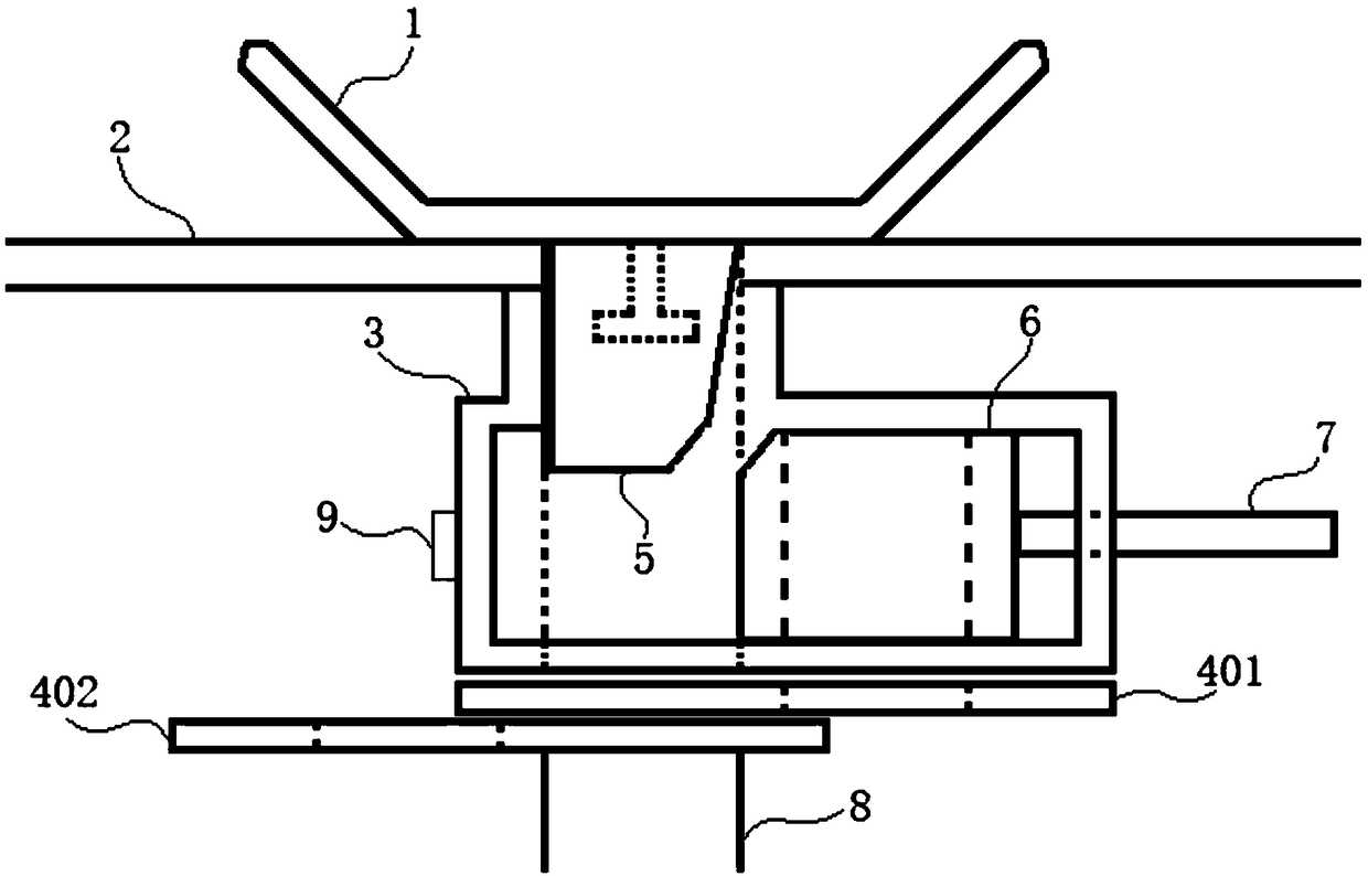
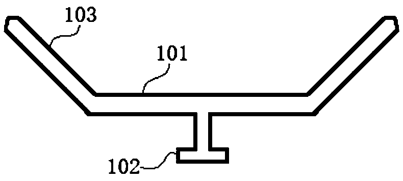
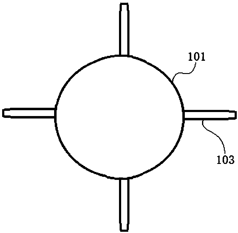
[0052] to combine Figure 1-6 , the ladle drain swirl suppressing device of the present embodiment comprises: a drainer 3, the upper end of the drainer 3 is provided with a drainer inlet 301, the lower end of the drainer 3 is provided with a drainer outlet 302, and the drainer 3 is self-drainer inlet 301 forms a drainage channel toward the outlet 302 of the diverter; the two sides of the diversion channel in the diverter 3 are respectively provided with a housing chamber 1 303 and a housing chamber 2 304; The lower end of the swirl 101 is connected with a T-shaped joint 102, the joint 102 is placed inside the nozzle plug 5, and the nozzle plug 5 can be inserted into the drainage channel from the inlet 301 of the diverter; The support member 103 that extends squarely; And drainage part 6, drainage part 6 is placed in accommodating chamber one 303, and one end of drainage part 6 is connected with push rod 7, and the other end of drainage part 6 is facing accommodating chamber tw...


PUM

PropertyMeasurementUnit
melting pointaaaaaaaaaa

Abstract

The invention discloses a steel ladle drainage method and relates to the field of steel ladle drainage devices in the steel and iron continuous casting production process. The steel ladle drainage method comprises the following steps that A, a steel ladle drainage and vortex suppression device is prepared; B, a drainage device and a water gap plug are mounted; C, a steel ladle is contained with molten steel; D, a drainage part is pushed to allow the water gap plug to be jacked upwards; E, the water gap plug is fused by the molten steel; F, the molten steel flows from the drainage part to a long water gap; and G, the molten steel at the final casting stage flows to a water gap at the bottom of the steel ladle from the parts between a plurality of strutting pieces of a vortex suppression device. The steel ladle drainage method aims at solving the problems that the purity degree of the molten steel is reduced due to the use of drainage sand in the existing continuous casting process, anda lot of casting residues of the steel ladle are formed in the final casting stage of the steel ladle; and with the adoption of the steel ladle drainage method, the use of the drainage sand in the steel ladle casting process is avoided, the purity degree of the molten steel is ensured, the height of slag of the molten steel is reduced, and the casting residues of the steel ladle are reduced.

Description

technical field [0001] The invention relates to the field of ladle drainage devices in the steel continuous casting production process, and more specifically relates to a ladle drainage method. Background technique [0002] In the continuous casting production process of iron and steel enterprises, in order to make the molten steel in the ladle flow out smoothly, it is necessary to fill the nozzle with a high melting point in the nozzle at the bottom of the ladle as drainage sand. When the slide plate of the nozzle is opened, the molten steel can flow The outflow of the drainage sand flows out, thus completing the pouring process. People have done a lot of research on the pouring performance of drainage sand, making the current pouring technology very mature. [0003] At present, the materials of commonly used drainage sand mainly include chromium, silicon, and forsterite. Among them, chromium drainage sand is most commonly used in iron and steel enterprises due to its high...

Claims


Application Information

Patent Timeline
Patent Type & Authority Applications(China)
IPC IPC(8): B22D41/48B22D41/00
CPCB22D41/00B22D41/48
Inventor 朱津津韦莉
Owner MAANSHAN SHANGYUAN METALLURGICAL TECH CO LTD
Why Eureka
Try Eureka