


Quick Research
Generate reliable direction feasibility study reports for your R&D in just a few steps.

Technical Q&A
Discover and master advanced knowledge NOW. Basics, ideas, possibilities, all at once.

Find Solutions
As an expert in R&D theories, this can generate solutions to your technical problems instantly.

Evaluate Feasibility
Analyze your overall solution with one click, know your potential R&D risks in advance.

Monitor Landscape
Get weekly tech updates, stay abreast of the latest tech innovations and key insights.
Plane far infrared injection drying assembly line
An assembly line, far-infrared technology, used in dry solid materials, dry goods handling, drying chambers/containers, etc., can solve problems such as material loss, difficult to disperse, material contamination, etc., to prevent collisions, pressure gradients and temperature gradients continue Stable and ensure the effect of continuous operation
- Summary
- Abstract
- Description
- Claims
- Application Information
AI Technical Summary
Problems solved by technology
Method used
Image

Examples
Embodiment 2
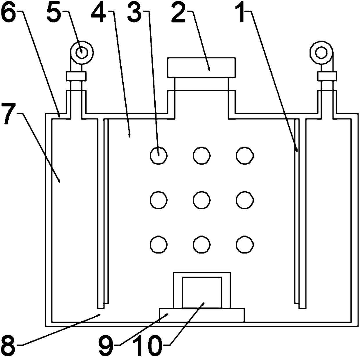
[0028] This embodiment is further improved based on embodiment 1, as figure 1 As shown, the tuyere 8 and the assembly line 9 are on a horizontal line.
[0029] During use, covering the inner wall of the drying box 4 with the infrared reflection plate 1 can increase the reflection effect of the inner wall of the drying box 4, thereby reducing heat loss caused by wall refraction and absorption.
Embodiment 3
[0031] This embodiment is further improved based on any one of Embodiments 1-2, such as figure 1 As shown, the inner wall surface of the drying box 4 is covered with an infrared reflective plate 1 .
[0032] During use, the tuyere 8 and the assembly line 9 form a horizontal line, so as to ensure that the infrared light can be reflected in the drying box 4 as much as possible, and it is not easy to go out from the tuyere 8, and the space is as close to a black body as possible while entering the air , and at the same time ensure to the greatest extent that even if the infrared light is lost, it is lost through the reflection of the material 10 .
Embodiment 4
[0034] This embodiment is further improved based on any one of embodiments 1-3, as figure 1 As shown, the side of the drying box 4 is covered with a casing 6, and there is a gap between the casing 6 and the side wall of the assembly line 9, and the gap is an air duct 7, and the air duct 7 blows hot air from top to bottom. The air duct 7 communicates with the drying box 4 through the tuyere 8 .
[0035] During use, the side wall of the drying box 4 is covered with a shell 6, an air duct 7 is formed between the shell 6 and the side wall, and hot air is ventilated in the air duct 7, so as to ensure that the side wall of the drying box 4 can be insulated and prevent the side wall from being damaged. The temperature is emitted in the form of heat conduction, which reduces the energy consumption for maintaining the temperature in the drying box 4, and the hot air passes through the air duct 7 from top to bottom, so that the hot air can preheat and heat the entire inner wall of the d...
PUM
 Abstract
Description
Claims
Application Information
 - R&D Engineer
- R&D Manager
- IP Professional
- Industry Leading Data Capabilities
- Powerful AI technology
- Patent DNA Extraction
Browse by: Latest US Patents, China's latest patents, Technical Efficacy Thesaurus, Application Domain, Technology Topic, Popular Technical Reports.
© 2024 PatSnap. All rights reserved.Legal|Privacy policy|Modern Slavery Act Transparency Statement|Sitemap|About US| Contact US: help@patsnap.com