
Unpowered ventilation device

A technology of power ventilation and exhaust pipes, applied in the field of ventilation, can solve the problems of cooling or heat loss, noise pollution, waste of energy, etc., achieve the effects of reducing heat loss, wide application range, and improving energy utilization

Active Publication Date: 2018-10-02
CHINA ACAD OF BUILDING RES
View PDF8 Cites 4 Cited by
  • Summary
  • Abstract
  • Description
  • Claims
  • Application Information

AI Technical Summary

Problems solved by technology

For buildings such as offices and residences without centralized fresh air, natural ventilation is mainly achieved by opening doors, windows, etc. to form drafts, but this will bring a series of negative effects
During the air-conditioning or heating season, opening doors and windows will cause a large amount of cold or heat loss, which is a serious waste of energy; if the doors and windows are closed, it is not conducive to replenishing fresh air, improving indoor air quality, and causing serious negative effects on people's physical and mental health. influences
In addition, if the building is close to the street, directly opening the doors and windows will cause greater noise pollution

Method used


Image

  • Unpowered ventilation device
  • Unpowered ventilation device
  • Unpowered ventilation device

Examples


Embodiment 1

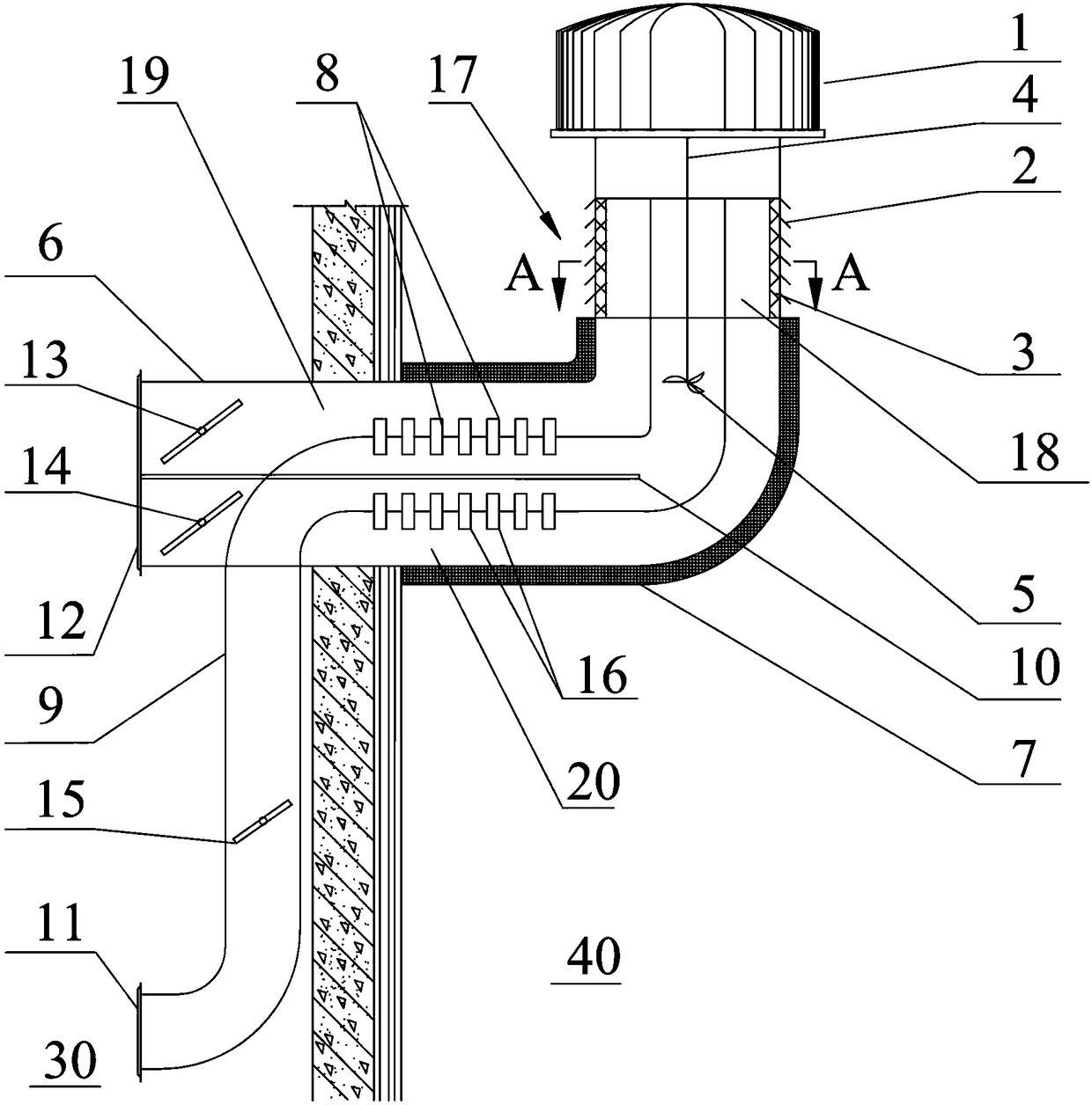
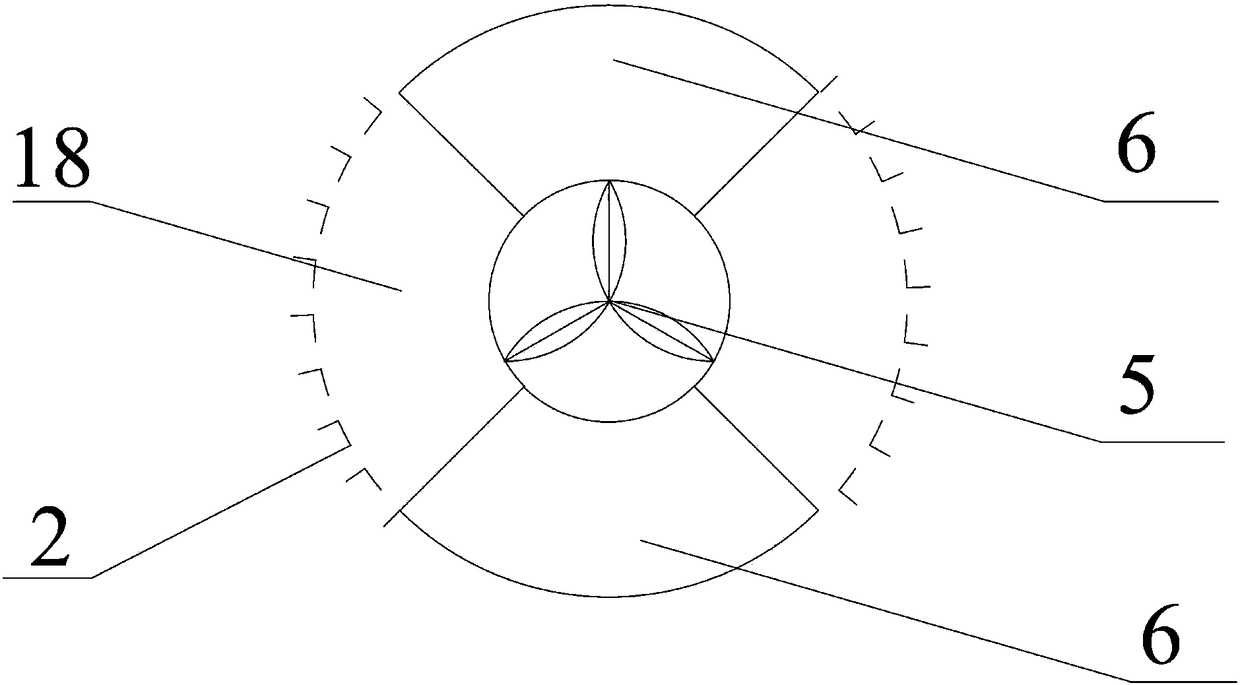
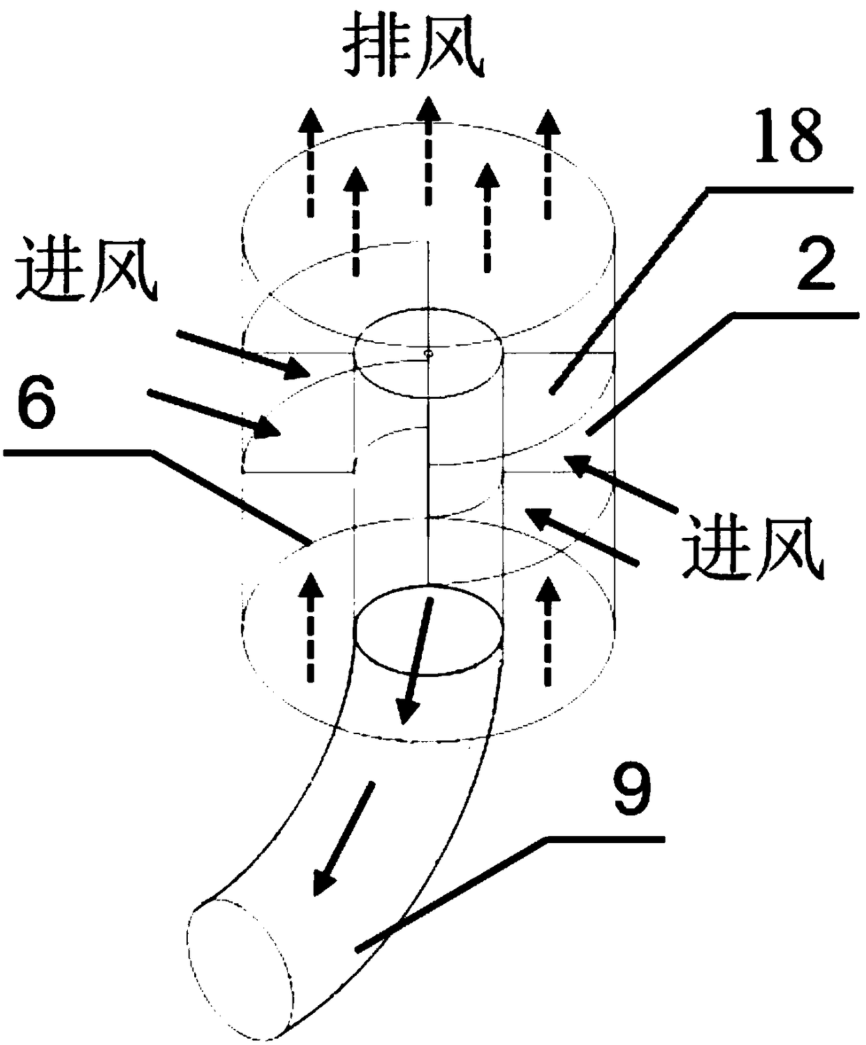
[0029] This embodiment provides a kind of unpowered ventilation device, such as Figure 1~3 As shown, it includes an exhaust pipe 6, an air inlet pipe 9, an impeller 5, a first heat pipe 8, a second heat pipe 16 and a partition 10. The exhaust pipe 6 is used to communicate with the indoor 30 and the outdoor 40, and the exhaust pipe 6 is located indoors. The end of 30 is provided with indoor exhaust port 12, and the end of exhaust pipe 6 located at outdoor 40 is equipped with rotating wind cap 1; Extend, the other end of the air inlet pipe 9 passes through the pipe wall of the exhaust pipe 6 and is located in the indoor 30 and extends to the indoor 30, the end of the air inlet pipe 9 is located at the outdoor 40, and the end of the air inlet pipe 9 is located at the end of the indoor 30 There is an indoor 30 air outlet 11, and the exhaust pipe 6 is located on the wall of the outdoor 40. There is an outdoor air inlet 17, and the outdoor air inlet 17 communicates with the air inl...


PUM


Abstract

The invention discloses an unpowered ventilation device. The unpowered ventilation device comprises an exhaust pipe, an air inlet pipe, an impeller, a first heat pipe, a second heat pipe and a separation plate; the exhaust pipe communicates an indoor space with an outdoor space; one end, which is located outdoors, of the exhaust pipe is provided with a rotary air cap; the air inlet pipe penetratesthrough the pipe wall, which is located indoors, of the exhaust pipe form the pipe, which is located outdoors, of the exhaust pipe and extends indoors; the pipe wall, which is located outdoors, of the exhaust pipe is provided with an outdoor air inlet which communicates with the air inlet pipe through a communication block; the impeller is arranged in the air inlet pipe and is connected onto therotary air cap through a transmission connection rod; the evaporation section and the condensation section of the first heat pipe are located on the inner and outer parts of the air inlet pipe; the condensation section and the evaporation section of the second heat pipe are located on the inner and outer parts of the air inlet pipe; the separation plate separates the first heat pipe from the second heat pipe and divides the exhaust pipe into a first exhaust passage and a second exhaust passage; and the first and second exhaust passages are internally provided with a first exhaust valve and a second exhaust valve correspondingly. By adopting the unpowered ventilation device, sufficient fresh air is provided for the indoor space; besides, the indoor heat loss can be lowered; and the utilization rate of energy is improved.

Description

technical field [0001] The invention relates to the technical field of ventilation, in particular to a non-powered ventilation device. Background technique [0002] Reasonable use of natural ventilation can adjust indoor thermal comfort, supplement fresh air, and create a healthy, comfortable and efficient working and living environment for people. For buildings such as offices and residences without centralized fresh air, natural ventilation is mainly achieved by opening doors, windows, etc. to form drafts, but this will bring a series of negative effects. During the air-conditioning or heating season, opening doors and windows will cause a large amount of cold or heat loss, which is a serious waste of energy; if the doors and windows are closed, it is not conducive to replenishing fresh air, improving indoor air quality, and causing serious negative effects on people's physical and mental health. influences. In addition, if the building is close to the street, directly o...

Claims


Application Information

Patent Timeline
IPC IPC(8): F24F7/00F24F12/00F24F13/10F24F13/30
CPCF24F7/00F24F12/002F24F13/10F24F13/30F24F2007/004F24F2012/005
Inventor 谢琳娜王清勤朱荣鑫张然孟冲李国柱
Owner CHINA ACAD OF BUILDING RES
Learn More