
High-quality powder recovery device

A recycling device, high-quality technology, applied in the field of 3D printing, can solve the problem of not being able to completely separate it, and achieve the effect of preventing oxidation and improving purity

Inactive Publication Date: 2018-10-02
安徽中健三维科技有限公司
View PDF8 Cites 4 Cited by
  • Summary
  • Abstract
  • Description
  • Claims
  • Application Information

AI Technical Summary

Problems solved by technology

[0003] Selected area laser melting is used to spread sufficient powder raw materials on the forming workbench by the internal powder spreading mechanism during work, and sinter them with lasers. After the forming is completed, a large amount of powder raw materials will be left on the internal workbench. Storage, when the powder is enough, put it into the vibrating sieve for screening, separate the powder raw material from the smoke and other impurities after sintering, there are many problems in the conventional recovery method, the high-temperature smoke and dust during part processing fall into the powder After cooling, it is bonded to the powder, and the vibrating sieve cannot completely separate it. The powder raw material is placed in the vibrating sieve to contact with the water vapor in the air, and finally it is recycled to the steel cylinder together with the air. As the storage time increases, the powder in the steel cylinder undergoes an oxidation reaction with the air. And go bad

Method used


Image

  • High-quality powder recovery device
  • High-quality powder recovery device

Examples


specific Embodiment approach

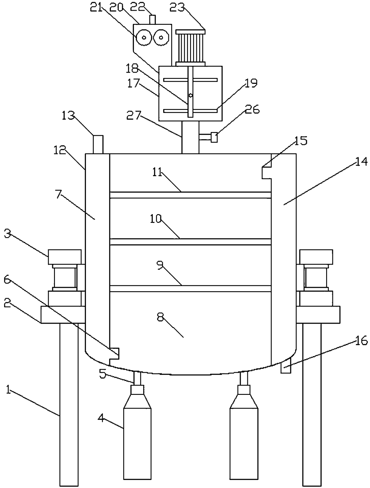
[0013] Figure 1-2 Show the specific embodiment of the present invention: a kind of high-quality powder recovering device, comprise the supporting leg 1 of ring table 2 and its bottom, described ring table 2 two ends are provided with vibrating motor 3, the vibrating motor 3 The output shaft is provided with a sieve box 12, and the sieve box 12 is respectively provided with a left cavity 7, a powder sieving cavity 8 and a right cavity 14, and the upper end of the sieve box 12 is provided with an air inlet pipe 13 communicating with the left cavity 7 , the bottom of the sieve box 12 is provided with an air outlet pipe 16 communicating with the right cavity 14 and a powder outlet pipe 5 communicating with the powder sieving chamber 8, the lower end of the powder outlet pipe 5 is connected with a recovery steel cylinder 4, and the left cavity The bottom of the 7 is provided with an air inlet 6 communicating with the powder sieving chamber 8, and the upper end of the right cavity ...


PUM


Abstract

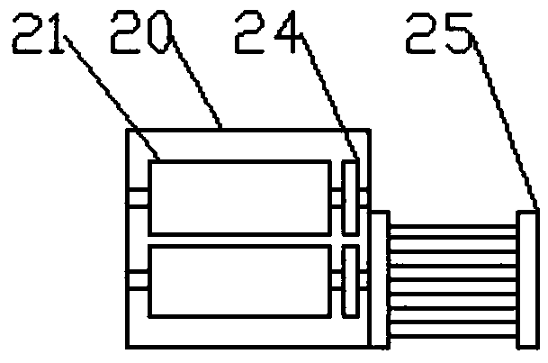
The invention discloses a high-quality powder recovery device. The device comprises an annular working table and supporting legs, wherein the supporting legs are arranged at the bottom of the annularworking table; vibration motors are arranged at the two ends of the annular working table, and output shafts of the vibration motors are provided with a screening box; a left cavity, a powder screening cavity and a right cavity are arranged in the screening box respectively; an air inlet pipe is arranged at the upper end of the screening box, and an air outlet pipe and powder outlet pipes are arranged at the bottom of the screening box; an air inlet hole is formed in the bottom of the left cavity, an air outlet hole is formed in the upper end of the right cavity, and a first screen, a secondscreen and a third screen are sequentially arranged in the powder screening cavity from top to bottom; a stirring box is arranged above the screening box, a first motor is fixed at the upper end of the stirring box, an output shaft of the first motor is connected to a stirring shaft, and a plurality of stirring rods are arranged on the stirring shaft; a grinding box communicating with the stirringbox is arranged at the upper end of the stirring box, two grinding wheels are arranged in the grinding box side by side, and gears meshed with each other are arranged at one ends of the grinding wheels; and a second motor is arranged on the side surface of the grinding box, and a powder feeding pipe is arranged at the upper end of the grinding box. According to the high-quality powder recovery device, the purity of the recovered powder is improved, and the storage period and the storage quality of the powder are prolonged.

Description

technical field [0001] The invention relates to the field of 3D printing, in particular to a high-quality powder recovery device. Background technique [0002] The laser rapid prototyping technology of metal powder is an effective way to manufacture complex parts, among which selective laser melting is one of the technologies with the most development potential. The selective laser melting technology combines CAD three-dimensional modeling, computer management The related technology uses CAD to establish a three-dimensional solid model, slices the three-dimensional solid model, imports the layered slice contour data into the computer, melts and solidifies the selected area layer by layer through laser, and accumulates layer by layer to finally form a solid part. [0003] Selected area laser melting is used to spread sufficient powder raw materials on the forming workbench by the internal powder spreading mechanism during work, and sinter them with lasers. After the forming i...

Claims


Application Information

Patent Timeline
Patent Type & Authority Applications(China)
IPC IPC(8): B22F3/105B33Y40/00B33Y30/00
CPCB22F3/003B33Y30/00B33Y40/00B22F10/00B01F27/90B22F10/73Y02P10/25
Inventor 张存柱
Owner 安徽中健三维科技有限公司
Learn More