Adsorption reactor and method for separating high-boiling-point coagulable components from mixed gas

A mixed gas and reactor technology, applied in separation methods, chemical instruments and methods, gas treatment, etc., to achieve simple and convenient operation, increase adsorption efficiency and desorption efficiency, and small working volume

Pending Publication Date: 2018-09-28
ZUNYI NORMAL COLLEGE
View PDF7 Cites 2 Cited by
  • Summary
  • Abstract
  • Description
  • Claims
  • Application Information

AI Technical Summary

Problems solved by technology

Therefore, in view of the existing problems in the prior art, it is urgent to provide a treatment technology for the separation of some components in the mixed gas with good adsorption effect, long regeneration cycle and convenient regeneration for the characteristics of the ultrafine fiber filler adsorbent. It is particularly important to solve the deficiencies in the prior art

Method used


Image

  • Adsorption reactor and method for separating high-boiling-point coagulable components from mixed gas
  • Adsorption reactor and method for separating high-boiling-point coagulable components from mixed gas
  • Adsorption reactor and method for separating high-boiling-point coagulable components from mixed gas

Examples


Embodiment 1

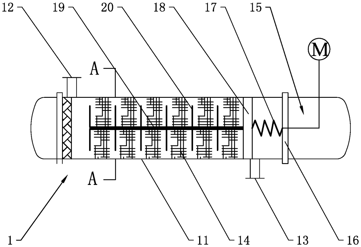
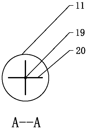
[0079] One of the implementations of an adsorption reactor for separating high-boiling condensable components in a mixed gas of the present invention, such as Figure 1 to Figure 2 It shows that the adsorption reactor 1 includes a cylindrical shell 11 and a front vent 12 and a rear vent 13 at both ends of the shell 11. The shell 11 is provided with a microfiber fabric filler 14 and a compacting device. The filler 14 is filled in the casing 11; the pressing device is placed at one end of the casing, including a driving unit and a pressing plate 18, and the driving unit drives the pressing plate 18 to compress or loosen the microfiber filler 14. It should be understood that the front vents 12 and the rear vents 13 at both ends of the housing 11 can be symmetrically distributed, and can also be appropriately adjusted according to the actual situation. Two front vents and two rear vents can be provided respectively, and two front vents The vents are the gas inlet for the mixed gas...

Embodiment 2

[0088] One of the implementations of an adsorption reactor for separating high-boiling condensable components in a mixed gas of the present invention, such as Figure 1 to Figure 2 express. The main technical solution of this embodiment 2 is basically the same as that of embodiment 1, and the features not explained in this embodiment 2 are explained in embodiment 1, and will not be repeated here. The difference between this embodiment and Embodiment 1 is that one end of the pressing plate 18 is provided with a plurality of pressing sheets which are flexibly connected and distributed in the filler of polyester microfiber fabric, and the diameter of the pressing sheets is smaller than that of the pressing plate 18 . Each compression sheet is connected with the pressing plate 18 through a belt connection or a chain connection, and the polyester microfiber fabric filler is filled between the compression sheets. When the pressing plate 18 compresses the polyester microfiber fabric ...

Embodiment 3

[0091] One of the implementations of an adsorption reactor for separating high-boiling condensable components in a mixed gas of the present invention, such as Figure 1 to Figure 2 express. The main technical solution of this embodiment 3 is basically the same as that of embodiment 1 or embodiment 2, and the features not explained in this embodiment 3 are explained in embodiment 1 or embodiment 2, and will not be repeated here. The difference between this embodiment and embodiment 1 or embodiment 2 is: because the mixed gas contains acid corrosive gas SO 2 , high concentration Br 2 (Br 2 The flue gas is a high boiling point condensable component), and the inner wall of the housing 11 is lined with a polytetrafluoroethylene anti-corrosion layer.

[0092] Specifically, the height / diameter ratio of the adsorption reactor is 10. Specifically, the driving unit is configured as a motor rack driving device. The motor is fixed at one end of the adsorption reactor, and the linear ...


PUM


Abstract

The invention provides an adsorption reactor for separating high-boiling-point coagulable components from mixed gas. The adsorption reactor for separating the high-boiling-point coagulable componentsfrom the mixed gas comprises a columnar reactor shell, a front ventilating opening and a rear ventilating opening, and the front ventilating opening and the rear ventilating opening are separately formed in the two ends of the shell. The adsorption reactor for separating the high-boiling-point coagulable components from the mixed gas is characterized in that an ultra-fine fiber filler and a pressing device are arranged in the adsorption reactor, and the ultra-fine fiber filler is filled in the shell; and the pressing device comprises a driving unit and a pressure plate, and the driving unit drives the pressure plate to press or loosen the ultra-fine fiber filler. The invention simultaneously provides a method for separating the high-boiling-point coagulable components from the mixed gas. The method comprises the following steps: when adsorption operation is carried out, driving the pressure plate to press the ultra-fine fiber filler by the driving unit; when desorption operation is carried out, driving the pressure plate to move reversely by the driving unit, and loosening the ultra-fine fiber filler; and carrying out coagulation treatment on the desorbed gas to obtain adsorbed matters which are separated and recycled. The adsorption reactor for separating high-boiling-point coagulable components from mixed gas has the advantages of high adsorption efficiency, long adsorbent regeneration period, convenience in regeneration and flexibility in operation.

Description

technical field [0001] The invention relates to the technical field of separation using a fixed adsorbent, in particular to an adsorption reactor and a method for separating high-boiling condensable components in mixed gases. Background technique [0002] The waste gas or gaseous by-products produced by industrial production are often multi-component mixed gases. The method of physical adsorption is an important method for separating certain / some components in a mixed gas. Commonly used adsorbents include activated carbon and molecular sieves. [0003] In addition, activated carbon fiber is also a widely used adsorbent, such as: Chinese invention patent (patent number: ZL2008 10114892.2) "Activated carbon fiber organic waste gas recovery method and system using nitrogen as desorption medium" provides a method of using activated carbon fiber and device systems. Traditional activated carbon, molecular sieves, and activated carbon fibers are all "rigid" adsorbents. After it...

Claims


Application Information

Patent Timeline
Patent Type & Authority Applications(China)
IPC IPC(8): B01D53/04
CPCB01D53/0407B01D2257/2022B01D2257/7027B01D2259/40083B01D2253/202
Inventor 肖菡曦汤建庭晁楚萱罗振宇周志强
Owner ZUNYI NORMAL COLLEGE
Why Eureka
Try Eureka