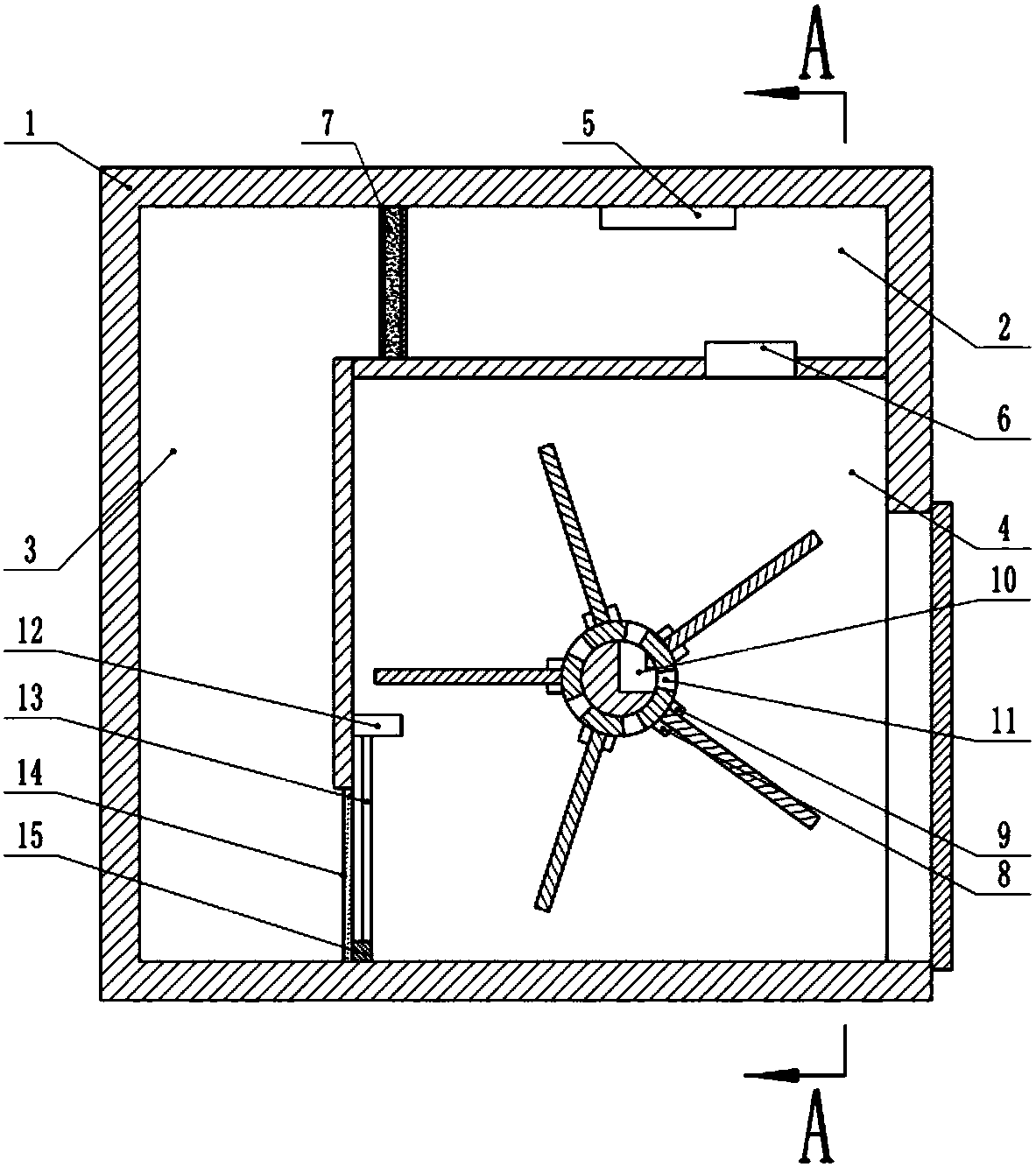
Wood material drying device
A drying device and wood technology, applied in drying, drying machine, wood drying, etc., can solve the problems of difficult guarantee of drying quality and low efficiency, and achieve improved drying quality and drying efficiency, good uniformity, The effect of weight reduction
Pending Publication Date: 2018-09-21
重庆草衣木食文化传播有限公司
View PDF7 Cites 9 Cited by
- Summary
- Abstract
- Description
- Claims
- Application Information
AI Technical Summary
Problems solved by technology
[0004] The purpose of the present invention is to provide a wood drying device to solve the problems of low efficiency and difficult guarantee of drying quality caused by outdoor drying of existing wood
Method used
View moreImage
Smart ImageViewing Examples
Examples
Embodiment Construction
[0014] The present invention will be described in further detail below by means of specific embodiments:
Login to View More PUM
 Abstract
The invention belongs to the technical field of wood material processing equipment, and particularly discloses a wood material drying device. The wood material drying device comprises a drying box, wherein a heating cavity, a circulation cavity and a drying cavity are arranged in the drying box, a fixing shaft is slidably connected with the interior of the drying cavity, an elastic piece is connected between the lower side of the fixing shaft and the lower part of the drying box, a power-off button is arranged above the fixing shaft, the fixing shaft is sleeved with a rotary shaft, and a plurality of arc-shaped grooves are formed in the two ends of the rotary shaft respectively; a first electromagnet is fixed in each arc-shaped groove, a second electromagnet is slidably connected with theinterior of each arc-shaped groove, a heat generator and an exhaust blower are arranged in the heating cavity, an air vent of the exhaust blower is located in the drying cavity, and the air vent is located in the right side of the rotary shaft; and a plurality of air cavities penetrating through the side wall of the rotary shaft is formed in the rotary shaft, the air cavities and the arc-shaped grooves are formed alternately, an air ventilation channel communicated with the air cavities is formed in the fixing shaft, and the two openings of the air ventilation channel are both located on the right side of the fixing shaft. The wood material drying device can drive wood materials to rotate and uniformly dry the wood materials, and meanwhile, automatic unloading of the wood materials and automatic shut down of the heat generator are achieved through the power-off button.
Description
technical field [0001] The invention belongs to the technical field of wood processing equipment, in particular to a wood drying device. Background technique [0002] Wood veneer, also known as veneer and veneer, is mainly used to produce artificial wood panels such as plywood, blockboard, formwork, and veneer. Wood veneer is divided into two types: rotary cutting and planing, and the veneer used for wood-based panels is mostly rotary cutting. Because the wood veneer produced by rotary cutting contains a lot of water, it needs to be dried before it can be used to produce artificial wood panels. [0003] The traditional drying method is to dry the rotary-cut wood veneers one by one in the sun, and dry the wood veneers through water evaporation. However, the disadvantage of this drying method is that it takes a lot of space and the production efficiency Low, the wood veneer after drying is easy to roll and deform, the quality is difficult to guarantee, and it is also subject...
Claims
Login to View More Application Information
Patent Timeline
 Patent Type & Authority Applications(China)
IPC IPC(8): F26B9/06F26B21/00F26B25/22
CPCF26B9/06F26B21/001F26B21/004F26B25/225F26B2210/16
Inventor 朱培钢
Owner 重庆草衣木食文化传播有限公司
Features
- Generate Ideas
- Intellectual Property
- Life Sciences
- Materials
- Tech Scout
- Unparalleled Data Quality
- Higher Quality Content
- 60% Fewer Hallucinations
Learn More Browse by: Latest US Patents, China's latest patents, Technical Efficacy Thesaurus, Application Domain, Technology Topic, Popular Technical Reports.
© 2025 PatSnap. All rights reserved.Legal|Privacy policy|Modern Slavery Act Transparency Statement|Sitemap|About US| Contact US: help@patsnap.com


