Ignition fuel oil flow control method for circled oil supply of auxiliary power unit

An auxiliary power unit, fuel flow technology, applied in engine control, fuel injection control, electrical control, etc., can solve problems such as failure to start, sudden drop in fuel pressure, and deterioration of fuel atomization, and achieve guaranteed ignition, reliable ignition, Good atomization effect

Active Publication Date: 2018-09-21
XIAN AVIATION COMPUTING TECH RES INST OF AVIATION IND CORP OF CHINA
View PDF5 Cites 2 Cited by
  • Summary
  • Abstract
  • Description
  • Claims
  • Application Information

AI Technical Summary

Problems solved by technology

[0009] In order to solve the problem that when the main oil circuit is connected during the starting process of the APU, due to the sudden increase of the fuel flow area, the fuel pressure will suddenly drop and the fuel atomization will deteriorate, which will cause the combustion chamber to stall and lead to the failure of starting, and an auxiliary power unit is proposed. Ignition Fuel Flow Control Method with Split Circle Fuel Supply

Method used


Image

  • Ignition fuel oil flow control method for circled oil supply of auxiliary power unit
  • Ignition fuel oil flow control method for circled oil supply of auxiliary power unit
  • Ignition fuel oil flow control method for circled oil supply of auxiliary power unit

Examples


Embodiment

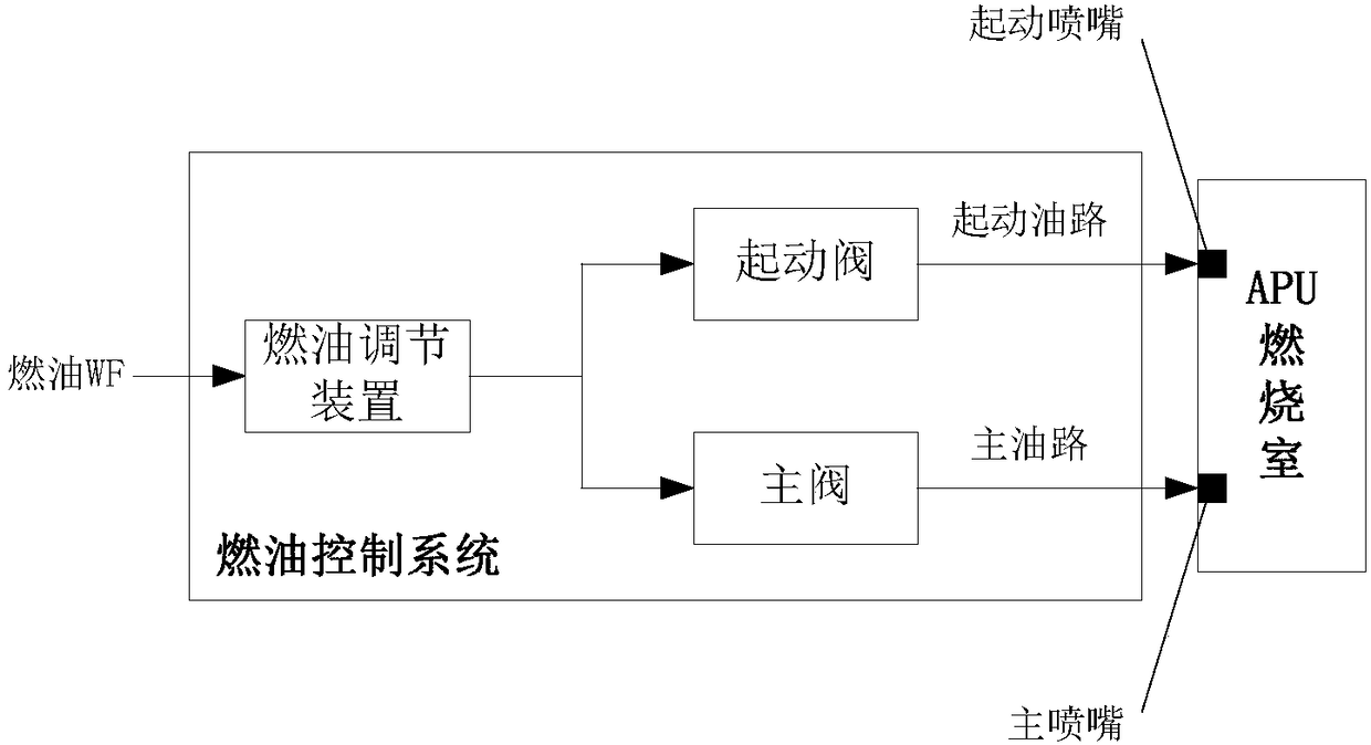
[0028] APU fuel control system such as figure 1 As shown, the fuel regulating device outputs fuel according to the control plan WF=F(NG, P1), and the main valve and the starting valve respectively control the on-off of the main oil circuit and the starting oil circuit. In the formula, NG is the speed of APU, P1 is the inlet pressure of APU, and WF is the fuel flow. In this example, the flow area of ​​the main oil circuit is large, and after the main valve is connected, the fuel pressure drops sharply, and it is very easy to stall.

[0029] The specific implementation steps and related parameters are as follows:

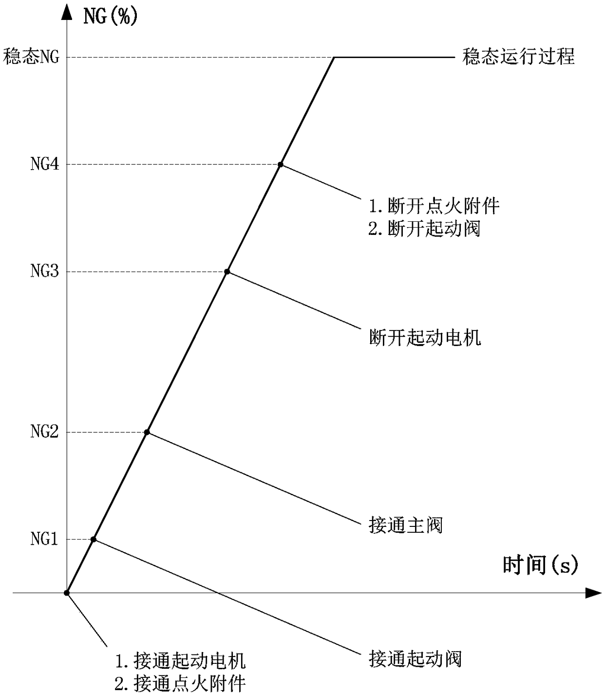
[0030] 1. The APU is in the prohibited state. After receiving the starting command, connect the starter motor and ignition accessories, and the starter motor will turn the APU;

[0031] 2. When the APU speed reaches 3%, record the exhaust temperature at this moment, record it as T40, connect the starting valve, and supply oil according to WF=F(NG, P1);

[0032] 3. ...


PUM


Abstract

The invention belongs to the technical field of aero-engine digital control, in particular to an ignition fuel oil flow control method for circled oil supply of an auxiliary power unit. The duty ratiocontrol mode is adopted, and in other words, the on/off state is achieved quickly through a switch; the auxiliary power unit (APU) is adjusted to start the fuel oil flow at the ignition stage; and the method aims at solving the problems that at the ignition stage of the APU, when a main oil way of a fuel oil distributor is on, due to the fact that the area of a fuel oil flow channel is increasedsuddenly, the fuel oil flow is excessively large, the fuel oil pressure is excessively low, fuel oil atomization is not conducted completely, a fire source formed when oil supply is conducted througha start oil way before the main oil way is on is extinguished by the excessive low pressure, and the flameout failure is caused in the start process. By means of the method, the fuel oil flow can be reduced, and the problems that when start is conducted under the upper air condition, the original constant flow of the APU start oil way is excessively large, and ignition cannot be achieved can be solved.

Description

technical field [0001] The invention belongs to the technical field of digital control of aero-engines, in particular to an ignition fuel flow control method for an auxiliary power unit that supplies fuel in circles. Background technique [0002] A large class of APU fuel control system, its structural principle is as follows figure 1 As shown, it consists of a fuel regulating device, a starting valve SFV and a main valve MFV. SFV and MFV respectively control the on-off of the starting oil circuit and the main oil circuit. The flow area of ​​the starting nozzle connected to the starting oil circuit is small, so that the starting oil circuit The fuel flow resistance is large, the flow rate is small, the atomization effect is good, and it is easy to form an ignition source; the flow area of ​​the main nozzle connected to the main oil circuit is large, and the fuel flow can be adjusted in a large range to adapt to large-scale fuel control. [0003] The timing control of this t...

Claims


Application Information

Patent Timeline
Patent Type & Authority Applications(China)
IPC IPC(8): F02D41/30
CPCF02D41/3076
Inventor 杨帆冯健朋周宇辰吕伟
Owner XIAN AVIATION COMPUTING TECH RES INST OF AVIATION IND CORP OF CHINA
Why Eureka
Try Eureka