Pressurized turbulent mixing device

A technology of pressurized pumps and deflectors, which is applied in the direction of fluid mixers, transportation and packaging, mixers, etc., and can solve problems such as the inability to form turbulent flow

Pending Publication Date: 2018-09-21
WENZHOU UNIVERSITY
View PDF5 Cites 3 Cited by
  • Summary
  • Abstract
  • Description
  • Claims
  • Application Information

AI Technical Summary

Problems solved by technology

[0005] The purpose of the present invention is to provide a pressurized turbulent flow mixing

Method used


Image

  • Pressurized turbulent mixing device
  • Pressurized turbulent mixing device
  • Pressurized turbulent mixing device

Examples


Embodiment 1

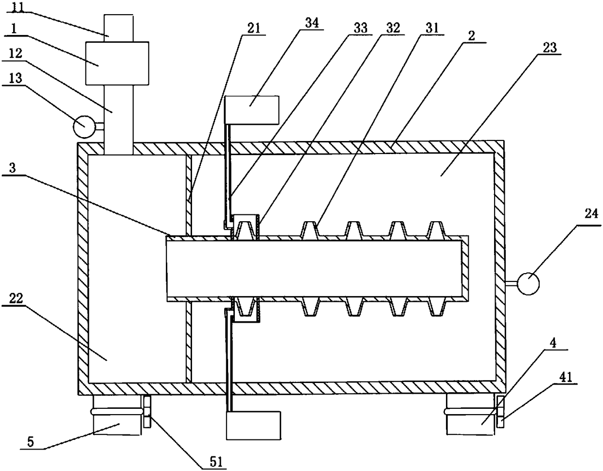
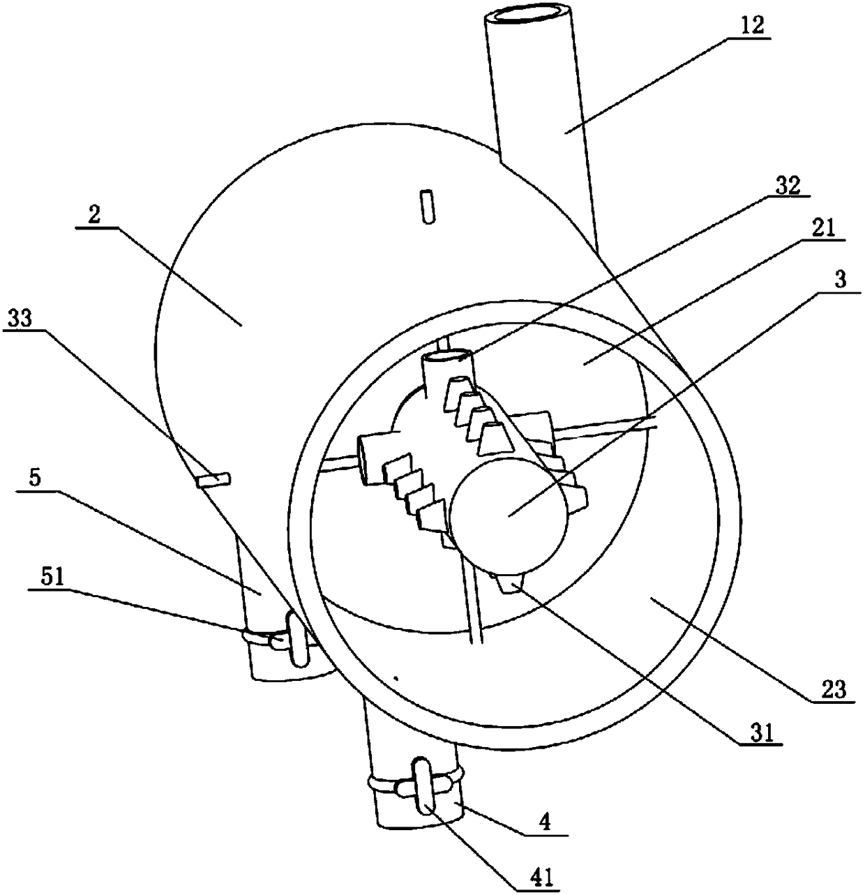
[0059] See figure 1 , figure 2 , a pressurized turbulent flow mixing device, including a pressurized pump 1, a suction pipe 11 and a liquid outlet pipe 12 arranged on the pressurized pump 1, and a cylinder 2 with both ends closed, and the inside of the cylinder 2 is A hollow tube 3 communicating with the inner cavity of the cylinder 2 is provided. The hollow tube 3 is provided with a nozzle 31 capable of spraying the inner surface of the cylinder 2. One end of the cylinder 2 is connected with the liquid outlet pipe 12, and the other end is provided with a There is output pipe 4.

[0060] Wherein, the nozzle can be a through hole or a nozzle protruding from the hollow tube.

[0061] The hollow tube communicates with the inner cavity of the column, that is, the hollow tube is provided with an opening, and the liquid in the column can enter the hollow tube through the opening.

[0062] When actually processing the liquid, the liquid to be processed enters the pressurized pump...

Embodiment 2

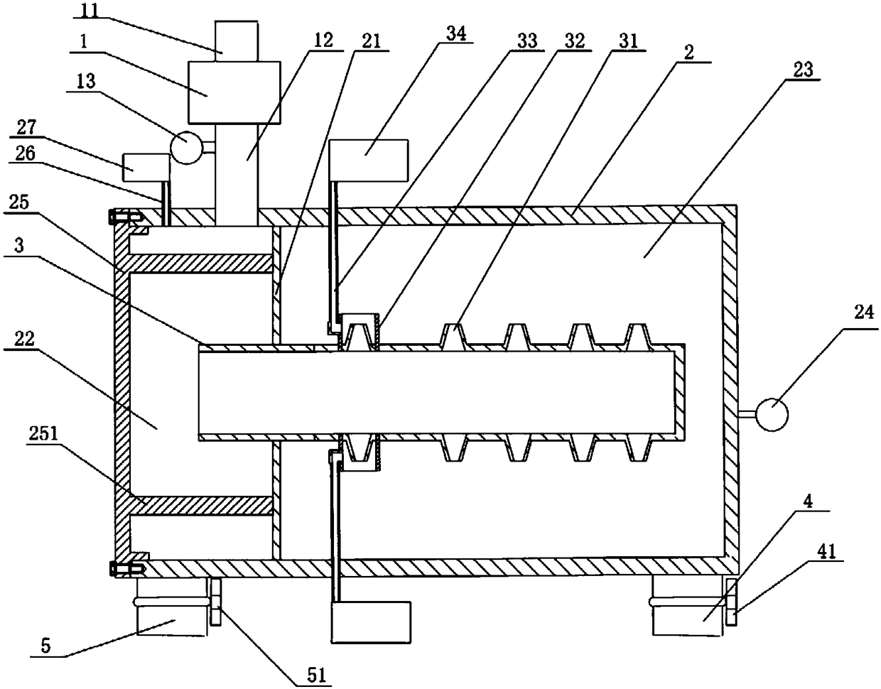
[0097] See image 3 , Figure 4 , also includes a left end cover 25, the left end cover 25 is arranged on the left end of the left chamber 22 and can make the left chamber 22 into an airtight setting, and the left end cover 25 is protruded with at least two deflectors arranged at intervals from the inner wall of the cylinder 2 251 , the deflectors 251 are distributed in a circular array with the axis of the left end cover 25 as the front, wherein one deflector 251 is arranged below the liquid outlet pipe 12 and inclined toward the liquid outlet pipe 12 . One end of the deflector 251 is fixedly connected to the left end cover 25 , and the other end is against the partition plate 21 . It also includes a vent pipe 26 and an air storage chamber 27 , the vent pipe 26 runs through the outer wall of the left chamber 22 , and one end is close to the nozzle of the liquid outlet pipe 12 , and the other end is connected to the air storage chamber 27 . All the other parts are the same a...


PUM


Abstract

The invention relates to a pressurized turbulent mixing device, which comprises a pressure pump and a liquid suction pipe and an outlet pipe arranged on the pressure pump, and further comprises a cylinder tube closed at both ends. A hollow pipe communicated with the inner cavity of the cylinder tube is arranged inside the cylinder tube. The hollow pipe is provided with a nozzle capable of sprayingthe inner surface of the cylinder tube. The pressure pump is provided with the liquid suction pipe used for introducing a treatment liquid and the outlet pipe communicated with the left end of the cylinder tube. One end of the cylinder tube is connected with the outlet pipe, and the other end of the cylinder tube is provided with an output pipe. By smoothly and continuously converting cell colonies such as cyanobacteria cells into scattered single cells through turbulent flow, water quality disasters of cyanobacteria blooms and the like can be effectively controlled. In addition, a pressurized liquid can be instantaneously mixed with other gases or liquids under the combined action of pressure and turbulent flow. The device of the invention can be applied to the occasions where the liquidneeds to be treated in the cosmetics and pharmaceutical fields.

Description

technical field [0001] The invention relates to the technical field of liquid processing devices, in particular to a pressurized turbulent flow mixing device. Background technique [0002] At present, eutrophication of water body has gradually become a major environmental problem affecting the people's livelihood, which can cause deterioration of water quality and damage the ecological environment. Among them, cyanobacterial blooms are a typical feature of eutrophic water bodies. At present, algae removal technologies at home and abroad are mainly divided into three categories: physical algae removal, chemical algae removal and biological algae removal. Physical algae removal technologies mainly include salvage, filtration, covering, air flotation, etc. Compared with other algae removal methods, physical algae removal is the most widely used. [0003] The current physical algae removal method mainly uses a liquid treatment device to carry out water-containing extraction, bo...

Claims


Application Information

Patent Timeline
IPC IPC(8): C02F1/50B01F5/02
CPCC02F1/50B01F25/2122B01F25/25B01F2101/305
Inventor 郝爱民井芹宁赵敏陈建鹰张祥雷徐明明高成吴明江
Owner WENZHOU UNIVERSITY
Why Eureka
Try Eureka