
Operation device for mixed material

A technology of operation device and unloading device, applied in the field of mechanical transmission, can solve the problems of poor work continuity and difficult to guarantee the accuracy of feeding amount, etc., and achieve the effect of improving compactness, reducing equipment complexity and accurate feeding amount.

Inactive Publication Date: 2018-09-21
芜湖拓云农业技术有限公司
View PDF4 Cites 1 Cited by
  • Summary
  • Abstract
  • Description
  • Claims
  • Application Information

AI Technical Summary

Problems solved by technology

The former type of method has the inherent shortcomings of traditional manual operations such as manpower consumption and low efficiency; There is a unique conveying path between the feed inlets, and since the raw materials fed into the kneading device have a fixed ratio, the running conveyor belt or pump can only be set to feed intermittently, that is, to and from the kneading device. After the noodle device conveys the material with a preset weight, it stops feeding, and when the mixing device is finished, the conveying device is turned on for the next transportation. Therefore, the work continuity is poor, and the accuracy of each feeding amount is difficult to guarantee.

Method used


Image

  • Operation device for mixed material
  • Operation device for mixed material
  • Operation device for mixed material

Examples


Embodiment 1

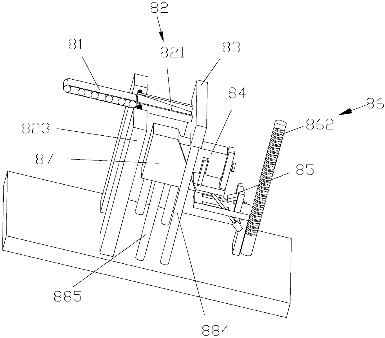
[0038] Such as Figure 1-2 As shown, the present invention discloses a mixed material running device, which includes a running conveyor belt 81, a flipping unloading device 82, a running baffle 83, a hopper 84, a running elastic device 85, and a running lifting device arranged sequentially from front to back. Abutment 86. The running conveyor belt 81 is used to convey the material to the turning-type unloading device 82 , and the running baffle 83 is in contact with the end of the upper turning-type unloading device 82 to confine the material in the turning-type unloading device 82 . The running baffle 83 of the present invention is supported by the fourth running frame 884 . The hopper 84 is located below the turning-type unloading device 82 , and the turning-type unloading device 82 rotates clockwise to discharge the materials therein into the hopper 84 . Also comprise operation guide table 87, the bottom of operation guide table 87 is supported by the 5th operation frame ...

Embodiment 2

[0042] Such as figure 1 , 5 As shown in -7, the difference between this embodiment and the above-mentioned embodiments is that: the flip-type unloading device 82 includes a running loading plate 821, a first running shaft 822, a first running frame 823, a first running torsion spring 824, and running The front end of the loading plate 821 is hinged with the first running shaft 822, the first running shaft 822 is arranged on the first running frame 823, and the first running torsion spring 824 is connected to the first running frame 823 and the bottom of the running charging plate 821. Between the front ends, the first running torsion spring 824 is assembled so that the rear end face of the running charging plate 821 is against the front end face of the running baffle plate 83; the running charging plate 821 includes a running bottom plate 8211 and two running side plates 8212 , the running bottom plate 8211 and two running side plates 8212 are surrounded by a structure with a...

Embodiment 3

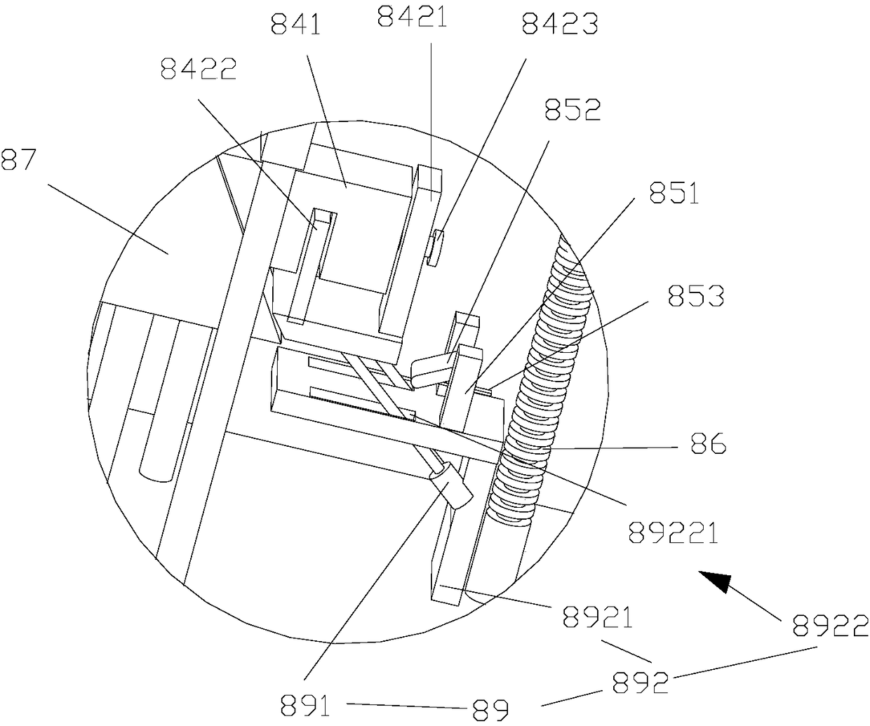
[0046] Such as figure 2 , 4 , shown in 6, the difference between the present embodiment and the above-mentioned embodiment is: the operation elastic device 85 comprises the second operation frame 851, the operation connecting plate 852, the operation protrusion 853, the second operation torsion spring 854, the second operation rotating shaft ( not shown in the figure). The second running shaft is arranged on the second running frame 851, the upper end of the running connecting plate 852 is hinged with the second running rotating shaft, and the second running torsion spring 854 is connected between the second running frame 851 and the upper end of running connecting plate 852 , the lower end of the running connecting plate 852 extends toward the direction of the hopper 84 , and the running protrusion 853 is mounted on the running connecting plate 852 . The oblique downward movement of the hopper 84 can drive the running connecting plate 852 to rotate until the running protru...


PUM


Abstract

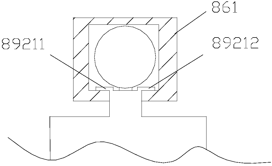
The invention discloses an operation device for a mixed material The operation device sequentially comprises an operation conveying belt, a turn-over type unloading device, an operation baffle, a conveyer bucket, an operation elastic device and an operation lifting base platform from front to back, and further comprises an operation guide table. The rear end surface of the operation guide table isan inclined guide surface which is gradually inclined backwards from top to bottom, the conveyer bucket is in sliding fit with the operation guide table, and the conveyer bucket can move in the guidedirection of the inclined guide surface of the operation guide table. The operation lifting base platform comprises an operation shell and an operation vertical screw rod, the operation vertical screw rod is limited in a cavity in the operation shell, an operation guide through groove is formed in the operation shell, and when the conveyer bucket obliquely moves downwards, a part of the operationelastic device can stretch into a rotary groove of the operation vertical screw rod through the operation guide through groove. The mixed material operation device has the advantages that the operation continuity is high, the single feeding quantity is precise, and the working efficiency is high.

Description

technical field [0001] The invention relates to the technical field of mechanical transmission, in particular to a mixed material running device. Background technique [0002] Maize (Latin name: Zea mays L.) is an annual herbaceous plant belonging to the family Poaceae Zea genus. Alias: corn, stick, corn, corn, millet, corn, corn, pearl rice, bract reed, big miliary millet, it is called pearl grain in Northeast Liaoning dialect, barley kernel in Chaozhou dialect, corn in Cantonese, and fan in Hokkien dialect. wheat. [0003] There are many types of corn varieties. According to their uses, there are grain-use varieties, vegetable varieties (including waxy type, sweet type, and corn shoots), processing varieties (sweet corn, corn shoots), and popping varieties ( Special varieties of popcorn), etc. The vitamin content in corn is very high, 5-10 times that of rice and wheat, and the nutritional value of special corn is higher than that of ordinary corn. The rich plant cellul...

Claims


Application Information

Patent Timeline
IPC IPC(8): B65G65/23B65G65/32B65G65/00
CPCB65G65/23B65G65/005B65G65/32B65G2201/04
Inventor 朱梁帅曾絮
Owner 芜湖拓云农业技术有限公司
Learn More