Mixing device of industrial tail gas purifying agent

A mixing device and industrial tail gas technology, which is applied in the direction of mixers, transportation and packaging, chemical instruments and methods, etc., can solve the problems of affecting the effect of tail gas purification, solution confusion, and out-of-control input ratio, so as to achieve convenient continuous work, convenient use, compact effect

Inactive Publication Date: 2019-04-02
浠水华杰窑炉设备有限责任公司
View PDF4 Cites 1 Cited by
  • Summary
  • Abstract
  • Description
  • Claims
  • Application Information

AI Technical Summary

Problems solved by technology

[0004] The purpose of the present invention is to solve the problems that the time required for the purification agent of the above-mentioned mixing device to be directly put into the mixing tank becomes longer and the input ratio of one of the reagents is out of control, which may easily cause confusion in the solution in the whole tank and affect the exhaust gas purification effect. A mixing device for industrial tail gas purification agent, which has the advantages of high mixing efficiency and avoiding the loss of control of the input amount of purification agent

Method used


Image

  • Mixing device of industrial tail gas purifying agent
  • Mixing device of industrial tail gas purifying agent
  • Mixing device of industrial tail gas purifying agent

Examples


Embodiment 1

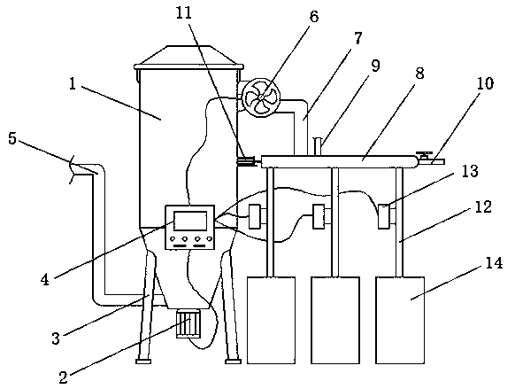
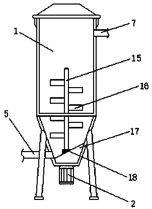
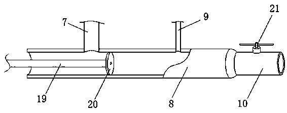
[0019] see Figure 1-2 Shown, a kind of mixing device of industrial tail gas purification agent comprises mixing barrel 1, liquid outlet pipe 5 and liquid inlet pipe 7, and the bottom end side wall of liquid outlet pipe 5 and mixing barrel 1 is pipeline connection, and liquid inlet pipe 7 and The top side wall of the mixing tank 1 is connected by pipelines, and the liquid inlet pipe 7 is controlled by the water pump 6 to pump liquid, the bottom of the mixing tank 1 is equipped with a motor 2, and the output end of the motor 2 is connected with the stirring rod 16 inside the mixing tank 1, The outer wall of the stirring rod 16 is welded with several stirring blades 16; one side of the mixing bucket 1 is placed on the ground with several reagent buckets 14, and the top of the reagent buckets 14 is connected to the suction pipe 12, and the several suction pipes 12 are all connected to the buffer tank 8. connected to each other, and a flow controller 13 is installed on the outer w...

Embodiment 2

[0021] In addition, refer to Figure 1-3 The outer wall of the mixing bucket 1 is equipped with a PLC controller 4, and the bottom of the mixing bucket 1 is welded with several supporting legs 3, and the supporting legs 3 support the mixing bucket 1 without shaking, and the PLC controller 4 is connected with the motor 2, the water pump 6, and the electric pusher Rod 11 is connected with flow controller 13, and the work of controlling motor 2, water pump 6, electric push rod 11 and flow controller 13 by PLC controller 4 can be more convenient. The output end of the motor 2 passes through the sealing ring 18 embedded in the slope bottom 17 and is connected to the stirring rod 15. The slope bottom 17 prevents the mixed cleaning agent inside the mixing bucket 1 from accumulating at the bottom of the bucket, and the sealing ring 18 prevents the mixed cleaning agent from flowing from the motor. The output end of 2 leaks out of the mixing tank 1, and the position of the end of the sl...


PUM


Abstract

The invention discloses a mixing device of an industrial tail gas purifying agent. The mixing device comprises a mixing barrel, a liquid outlet pipe and a liquid inlet pipe; the liquid outlet pipe isconnected with the side wall of the bottom end of the mixing barrel through a pipeline; the liquid inlet pipe is connected with the side wall of the top end of the mixing barrel through a pipeline; and the liquid inlet pipe controls liquid pumping through a water pump. A buffer tank is installed between the liquid inlet pipe of the mixing barrel and reagent barrels, and the buffer tank is used forstoring purifying agent solutions pumped from the reagent barrels and carrying out pre-mixing, so that remixing in the mixing barrel is facilitated; a liquid pumping pipe of each reagent barrel is provided with a flow controller, and the flow controllers are used for controlling the flow of the purifying agents in the reagent barrels, so that all the purifying agents can enter the buffer tank according to proportions. Even if one of the flow controllers breaks down, the purifying agent can only be stored in the buffer tank and does not quickly enters the mixing barrel, so that the problem that the proportion of the purifying agents is disordered due to equipment faults can be avoided. The mixing device provided by the invention has the advantage of better mixing effect.

Description

technical field [0001] The invention relates to a mixing device, in particular to a mixing device for an industrial tail gas purifying agent, and belongs to the technical field of tail gas treatment. Background technique [0002] The industrial tail gas is purified by the tail gas treatment device under the action of the catalyst to reduce the pollution to the environment. However, the general purification requires the use of purifiers. Since the proportion of each purifier is different, it needs to be carried out through a mixing device in advance. Mixing, so that the exhaust gas can be purified when it is put into the exhaust gas treatment device. [0003] When each purifier is mixed, a mixing device is used to mix the purifier solution in proportion. When the purifier is drawn out from the reagent tank, it is controlled by the flow controller. Generally, a stirring rod is installed inside the mixing tank to stir and mix the purifier solution. Traditionally The cleaning a...

Claims


Application Information

Patent Timeline
Patent Type & Authority Applications(China)
IPC IPC(8): B01F13/10B01F15/00B01F15/04
CPCB01F33/821B01F35/1452B01F35/883
Inventor 蔡德华占细见程丹
Owner 浠水华杰窑炉设备有限责任公司
Why Eureka
Try Eureka