
Multi-coil coupling non-mold electromagnetism incremental forming device and method

An incremental forming, multi-coil technology, applied in the field of electromagnetic incremental forming, can solve the problems that the blank holder force cannot be flexibly adjusted, the need for molds, and the high production cost, so as to shorten the production cycle of the mold, avoid uneven flow levels, and save processing costs. Effect

Active Publication Date: 2018-09-21
HUAZHONG UNIV OF SCI & TECH
View PDF5 Cites 2 Cited by
  • Summary
  • Abstract
  • Description
  • Claims
  • Application Information

AI Technical Summary

Problems solved by technology

However, this method requires molds, complex forming devices, high production costs, and long trial period; during the forming process, the sheet material will collide with the surface of the mold, which leads to poor surface quality of the parts and springback; this method can only produce For simple shell parts, such as hemispherical shell parts, this method is powerless for parts with both convex and concave structures or wavy structures on the surface; in addition, this method provides blank-holding force by fastening the plate with screws, The size of the edge force cannot be adjusted flexibly, which affects the forming quality of the part

Method used


Image

  • Multi-coil coupling non-mold electromagnetism incremental forming device and method
  • Multi-coil coupling non-mold electromagnetism incremental forming device and method
  • Multi-coil coupling non-mold electromagnetism incremental forming device and method

Examples


Embodiment Construction

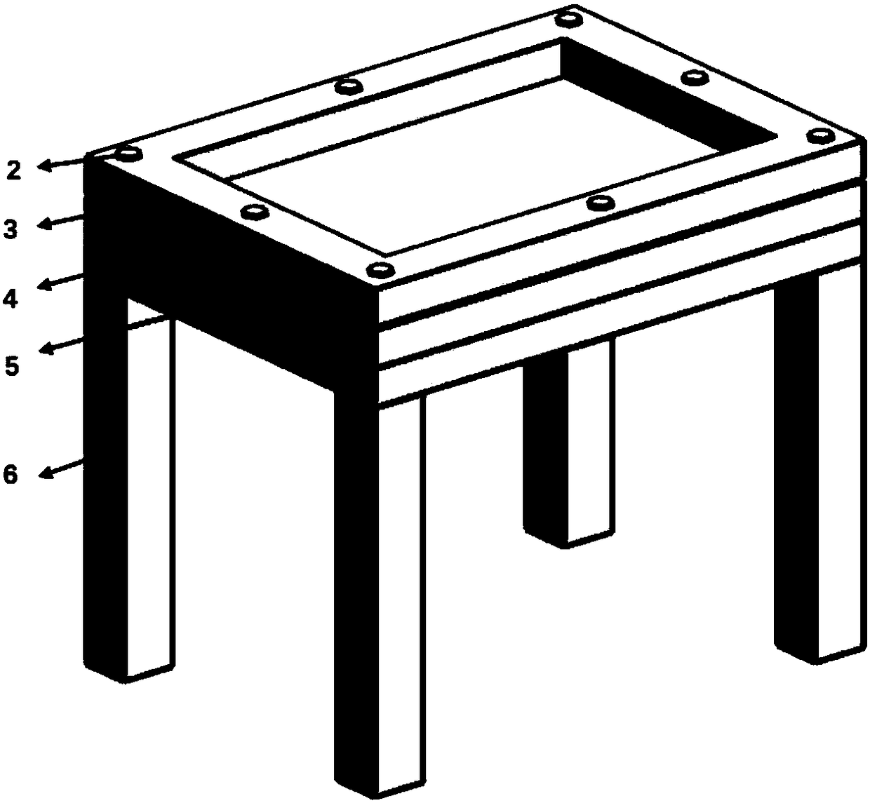
[0038] In order to make the object, technical solution and advantages of the present invention clearer, the present invention will be further described in detail below in conjunction with the accompanying drawings and embodiments. It should be understood that the specific embodiments described here are only used to explain the present invention, not to limit the present invention. In addition, the technical features involved in the various embodiments of the present invention described below can be combined with each other as long as they do not constitute a conflict with each other.

[0039] figure 1 It is a flow chart of the dieless electromagnetic progressive forming process of variable blank holder force constructed according to the preferred embodiment of the present invention, as shown in figure 1 As shown, the present invention provides a multi-coil coupling modeless electromagnetic progressive forming device, method and device, which includes the following steps:

[...


PUM

PropertyMeasurementUnit
thicknessaaaaaaaaaa
thicknessaaaaaaaaaa

Abstract

The invention belongs to the field of electromagnetism incremental forming, and discloses a multi-coil coupling non-mold electromagnetism incremental forming device and method. The method comprises the steps that (a) the non-mold electromagnetism incremental forming device is provided, and the device comprises a plurality of form-wound coils and a plurality of upper and lower built-in coils; (b) afinite element model of the non-mold electromagnetism incremental forming device is constructed to simulate an electromagnetism incremental process of to-be-formed board materials, so that simulationparameters of simulated forming parts and simulation parameters of the form-wound coils and built-in coils in the finite element model are acquired; (c) the to-be-formed board materials are placed among the built-in coils, according to the simulation parameters obtained in the step (b), corresponding parameters are set to achieve compression and electromagnetism incremental forming of the to-be-formed board materials, therefore a preforming part is acquired; (d) the form-wound coils at the upper and lower sides are selected from all the form-wound coils, so that the forming coils move along the forming hook face of the preforming part to carry out shaping. By adopting the method, the forming device has light weight, and the acquired part is good in the surface quality and high in formingaccuracy.

Description

technical field [0001] The invention belongs to the field of electromagnetic progressive forming, and more specifically relates to a multi-coil coupling modeless electromagnetic progressive forming device and method. Background technique [0002] Lightweight is an inevitable trend in the development of contemporary industry. There are generally two ways to achieve lightweight: structural lightweight and material lightweight. Lightweight alloys are typical lightweight materials. At present, aluminum alloys, magnesium alloys, etc. have received a lot of attention. However, due to the poor formability of these light alloys at room temperature, this severely limits the large Scale application. Electromagnetic forming technology provides a new and effective method for the plastic processing problem of such lightweight alloys. Electromagnetic forming is a high-speed forming process. Under the coupling effects of electric field, magnetic field and temperature field, the material ...

Claims


Application Information

Patent Timeline
Patent Type & Authority Applications(China)
IPC IPC(8): B21D31/00
Inventor 赵明杰冯飞李建军黄亮袁鹏肖望刘贤龙苏红亮张启宪黄攀
Owner HUAZHONG UNIV OF SCI & TECH
Learn More