
Hopkinson press rod system with true triaxial dynamic loading and testing functions and method

A technology of dynamic loading and testing functions, applied in the testing/calibration of velocity/acceleration/shock measurement equipment, velocity/acceleration/shock measurement, measurement devices, etc., which can solve the problems of dynamic calibration, difficult decoupling, and synchronization of shock wave structure It can solve the problems of complex shape consistency, etc., to achieve the effect of wide range of applications, high measurement accuracy, and avoidance of decoupling structures.

Active Publication Date: 2018-09-18
NORTHWESTERN POLYTECHNICAL UNIV
View PDF5 Cites 17 Cited by
  • Summary
  • Abstract
  • Description
  • Claims
  • Application Information

AI Technical Summary

Problems solved by technology

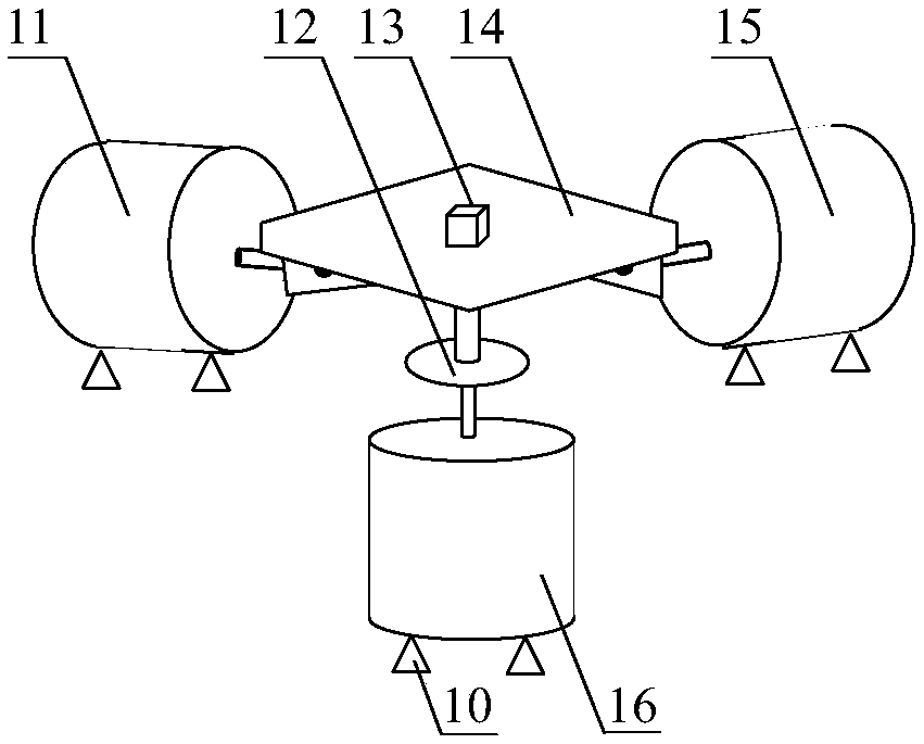
refer to figure 2 The adjustable three-axis calibration table can realize the three-axis calibration of the dynamic characteristics of general accelerometers with low g value. On the one hand, because the excitation signal with too high g value cannot be generated, for high g Accelerometers cannot perform full-scale dynamic calibration; on the other hand, in order to achieve simultaneous loading in three directions, this kind of three-axis calibration platform needs to design a very complex decoupling structure bearing platform, so that the respective loading directions do not affect each other. , this platform is equipped with an accelerometer, it is difficult to achieve ideal three-way decoupling in actual operation
At the same time, it is very complicated to realize the synchronization of independent loading in the three-axis direction and the consistency of shock wave configuration.

Method used


Image

  • Hopkinson press rod system with true triaxial dynamic loading and testing functions and method
  • Hopkinson press rod system with true triaxial dynamic loading and testing functions and method
  • Hopkinson press rod system with true triaxial dynamic loading and testing functions and method

Examples


specific Embodiment

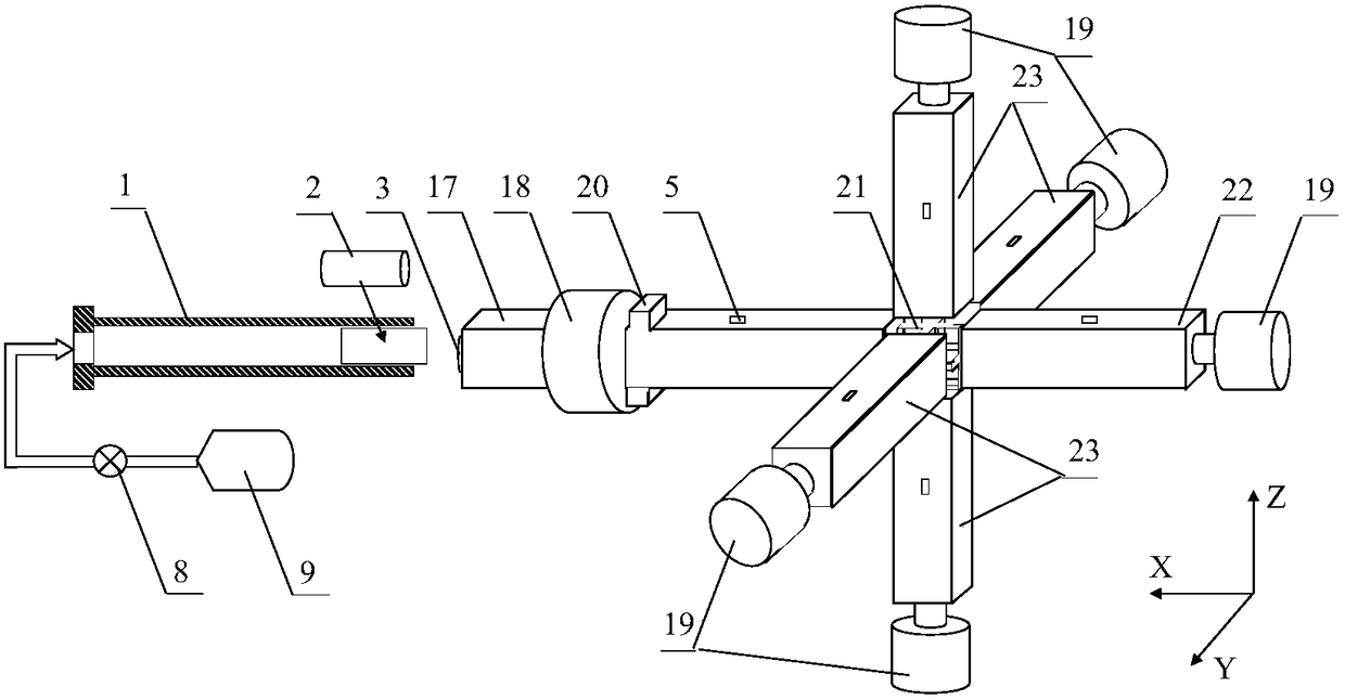
[0034] refer to image 3 and Figure 4 , the present invention adopts the square prism titanium alloy rod of sectional side length 30mm, length 1800mm as incident rod 17 (also can adopt different material hollow tube, circular cross-section rod according to needs), and the incident rod pressurization is set at the distance from the incident rod end 700mm The boss 20 is used for the hydraulic servo control system 18 to pressurize the injection rod. The main shaft transmission rod 22 and the secondary shaft transmission rod 23 are tetragonal prism titanium alloy rods with a section side length of 30 m and a length of 1200 mm (hollow tubes of different materials and circular cross-section rods can also be used as required). The roughness of all waveguide rods is 0.8, and the coaxiality and straightness are within 0.05mm deviation per meter. A pair of 120 ohm strain gauges 5 are pasted on the upper and lower surfaces of the six waveguide rods at a distance of 600 mm from the ela...


PUM


Abstract

The invention relates to a Hopkinson press rod system with true triaxial dynamic loading and testing functions and a method. By using a true triaxial Hopkinson rod device, and imposing a controllablesingle-shaft impact overload on a fixed substrate (basis) of a triaxial high g value accelerometer, by use of the Poisson effect of an elastic substrate, synchronous overload is generated in other twovertical (auxiliary axes Y and Z) directions which are perpendicular to the loading (main axis X) direction. Based on a triaxial direction elastic rod, the accelerator triaxial g value response is acquired, so it is achieved that dynamic calibration is simultaneously performed on the triaxial high g value accelerometer in three orthogonal directions. The beneficial effects are that the Hopkinsonpress rod system is not only an excitation signal generator, but also a signal acquirer. Thus, a complex decoupling structure can be avoided; simultaneous loading in three directions can be achieved;single-axis or bi-axis dynamic characteristic calibration can be performed; and the system is widely applicable, simple in operation, high in repeatability and high in measurement precision.

Description

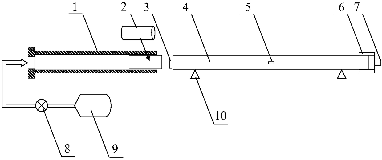
technical field [0001] The invention belongs to the true three-axis dynamic calibration technology of a three-axis high-g value accelerometer, and relates to a Hopkinson pressure bar system and method with true three-axis dynamic loading and testing functions. The fixed base (foundation) of the high-g value accelerometer applies a controllable uniaxial impact overload, using the Poisson effect of the elastic base, in the other two vertical directions (secondary axis Y and Synchronous overload is generated in the Z) direction, and the three-axis g-value response of the accelerometer is obtained by means of the elastic rod in the three-axis direction, so as to realize the simultaneous dynamic calibration of the three-axis high-g-value accelerometer in three orthogonal directions. Background technique [0002] refer to figure 1 , Literature: Yuan K, Guo W, Su Y, et al. Study on several key problems inshock calibration of high-g accelerometers using Hopkinson bar[J]. Sensors an...

Claims


Application Information

Patent Timeline
Patent Type & Authority Applications(China)
IPC IPC(8): G01P21/00
CPCG01P21/00
Inventor 郭伟国袁康博李鹏辉
Owner NORTHWESTERN POLYTECHNICAL UNIV
Learn More