
Error detection and separation method of high-precision laser measurement system

A laser measurement system and error detection technology, applied in the direction of measurement devices, optical devices, instruments, etc., can solve the problems of inability to detect and separate the measurement system structure, complex system structure, expensive price, etc., to achieve convenient operation and measurement accuracy High and low cost effect

Active Publication Date: 2018-09-18
DALIAN UNIV OF TECH
View PDF8 Cites 7 Cited by
  • Summary
  • Abstract
  • Description
  • Claims
  • Application Information

AI Technical Summary

Problems solved by technology

Although these methods can reduce the drift error of the laser beam, the active compensation technology of the high-precision laser source and piezoelectric ceramic feedback control system will make the system structure complex and expensive. The main problem is that these methods can only solve the problem of laser beam drift. problem, inability to detect and isolate errors in the measurement system structure

Method used


Image

  • Error detection and separation method of high-precision laser measurement system
  • Error detection and separation method of high-precision laser measurement system
  • Error detection and separation method of high-precision laser measurement system

Examples


Embodiment Construction

[0018] The following will clearly and completely describe the technical solutions in the embodiments of the present invention with reference to the drawings in the embodiments of the present invention.

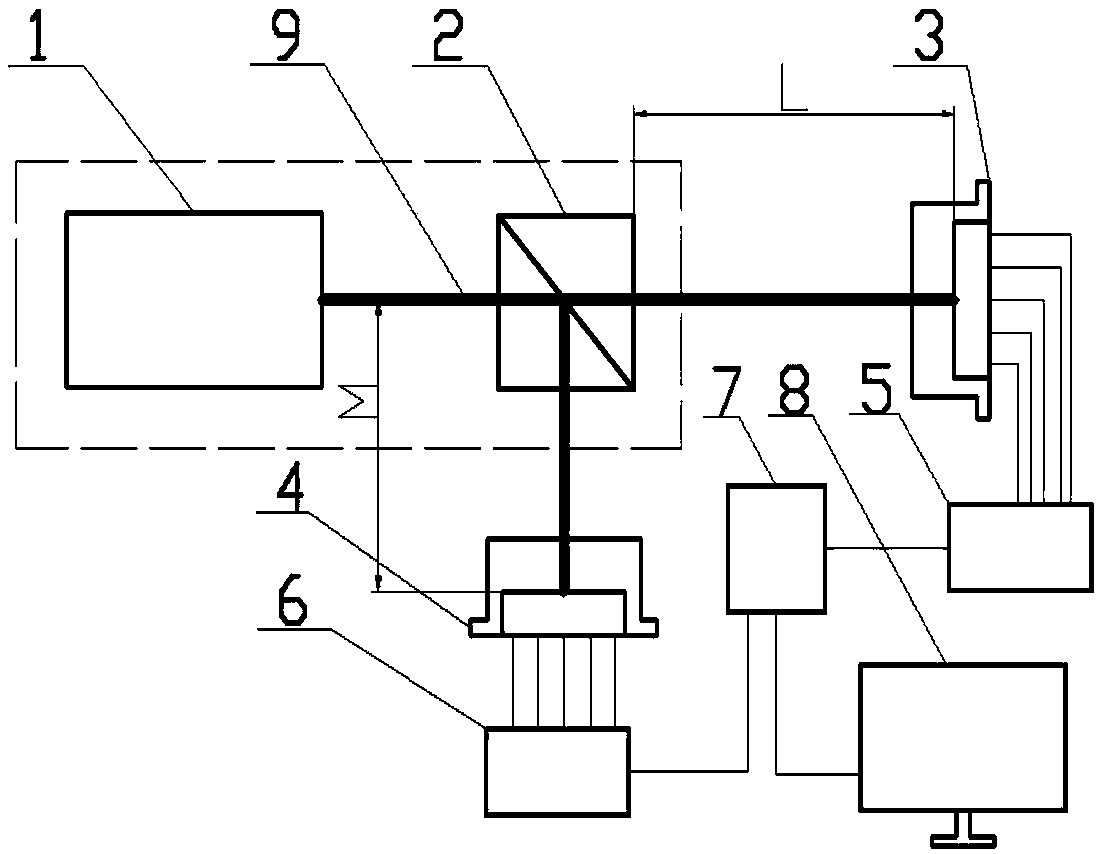
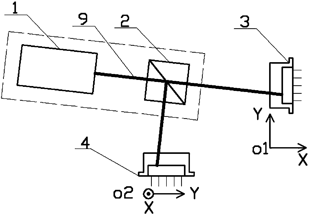
[0019] Use an ordinary semiconductor laser with a power of 5mW and a beam diameter of 3mm as the light source. The beam is irradiated vertically on the surface of the beam splitter prism, and the laser beam is split into two beams at 90 degrees. Location. The distances L and M from the beam splitting prism to the four-quadrant detector ① and the four-quadrant detector ② are 150mm.

[0020] Four-quadrant detectors such as Figure 4 The photosensitive part shown is divided into four parts, and the four quadrants A, B, C, and D are respectively named along the counterclockwise direction. The current generated by each quadrant after laser irradiation is I A , I B , I C , I D , the output current through the current conversion board is converted to the corresponding voltage V ...


PUM

PropertyMeasurementUnit
Poweraaaaaaaaaa
Beam diameteraaaaaaaaaa

Abstract

The invention discloses an error detection and separation method of a high-precision laser measurement system. Total errors include laser beam drift errors of high-precision laser measurement and measurement system structural errors, wherein the laser beam drift errors comprise flat floating, angular floating and random drifting of laser beams. The errors refer to micro deformations generated by the fact that the system structure and tools are affected by the environment. Accuracy and stability of laser precision measurement will be seriously affected. According to the invention, by establishing a mathematical mode of the laser measurement system errors, and using a special device combining a laser source and a four-quadrant detector, the total errors of the high-precision laser measurement system are detected, and the laser beam drifting errors and the system structural errors are calculated and separated.

Description

technical field [0001] The invention relates to an error detection and separation method of a high-precision laser measurement system, and the method is mainly used in the error detection and compensation of laser precision measurement. Background technique [0002] Laser precision measurement technology is widely used in the field of high-precision size and angle measurement by virtue of high-performance and stable measurement accuracy (high-precision machine tool processing error detection, precision equipment multi-degree-of-freedom detection, large-size long-distance guide rail straightness measurement, alignment measurement, etc.) . At present, high-precision laser measurement systems usually use expensive low-drift laser sources to reduce the laser beam drift error of the measurement system, and compensate the laser beam drift error by adjusting the attitude of the laser beam mirror of the measurement system through feedback control of piezoelectric ceramic micro-posit...

Claims


Application Information

Patent Timeline
IPC IPC(8): G01B11/00
CPCG01B11/00
Inventor 郭正刚李泽孙阳阳张良牛帅旗冯盼州徐董辉
Owner DALIAN UNIV OF TECH
Learn More