
Tearing instrument for corneal posterior lamella in ophthalmology

A technology of cornea and posterior plate, which is applied in ophthalmic surgery, laser surgery, etc., can solve the problems that have not been disclosed, and achieve the effect of smooth operation, increased contact area, and easy operation

Pending Publication Date: 2018-09-18
SHANGHAI TONGJI HOSPITAL
View PDF2 Cites 0 Cited by
  • Summary
  • Abstract
  • Description
  • Claims
  • Application Information

AI Technical Summary

Problems solved by technology

[0007] However, the above-mentioned patent documents have not been disclosed about the technical solutions that can be used to tear the descemet membrane through the anterior chamber in ophthalmic microsurgery, and can play an auxiliary reverse fixation effect on the anterior chamber during the operation.
[0008] To sum up, there is an urgent need for a set of special corneal posterior lamellar tearing instruments, which can tear the corneal posterior lamellar through the anterior chamber, and can assist in reverse fixation of the cornea during surgery, enabling deep lamellar keratoplasty. A tearing device that avoids secondary keratoplasty in cases of residual corneal posterior lamellar opacity and does not cause decompensation of corneal endothelial function has not been reported yet

Method used


Image

  • Tearing instrument for corneal posterior lamella in ophthalmology
  • Tearing instrument for corneal posterior lamella in ophthalmology
  • Tearing instrument for corneal posterior lamella in ophthalmology

Examples


Embodiment Construction

[0039] The present invention will be further described below in conjunction with the embodiments and with reference to the accompanying drawings.

[0040] The reference signs and components involved in the accompanying drawings are as follows:

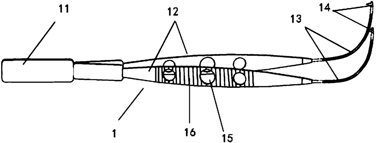
[0041] 1. Tear-off forceps 11. Forceps handle

[0042] 12. Tweezers arm 13. Inclined clamp arm

[0043] 14. Tweezers 141. Upper single tooth

[0044] 142. Double teeth at the lower end 15. Round hole

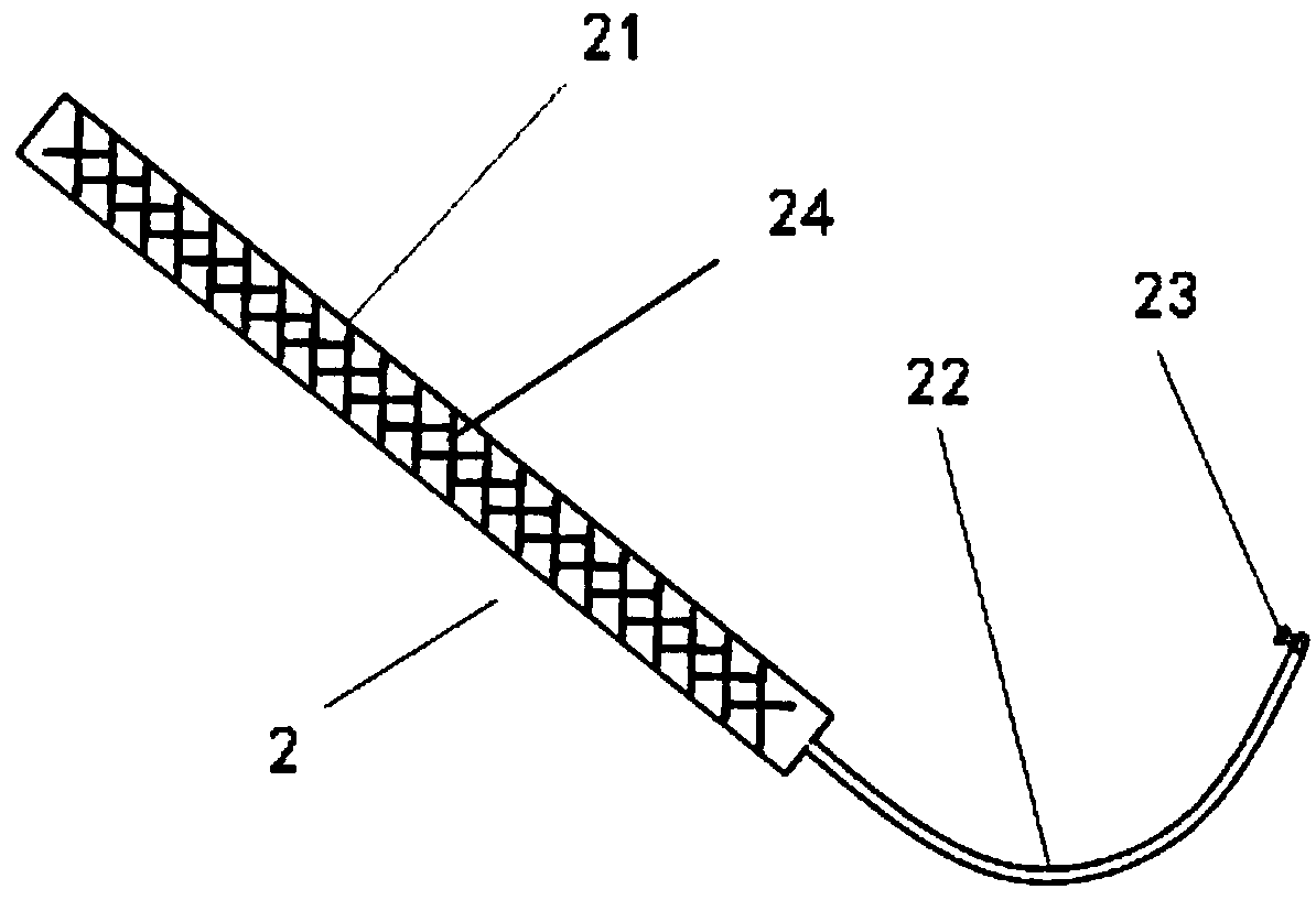
[0045] 16. Three-dimensional stripes 2. Auxiliary hook

[0046] 21Hook handle 22.Hook arm

[0047] 23. Hook head 231. Blunt round platform

[0048] 232. Thin Neck 24. Stereo Mesh

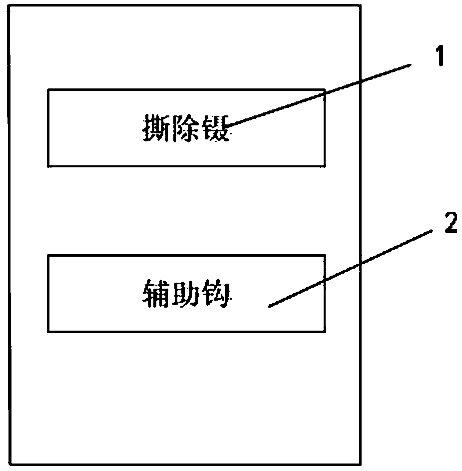
[0049] Please refer to figure 1 , figure 1 It is a structural block diagram of a corneal posterior lamellar tearing instrument of the present invention. The ophthalmic corneal posterior lamellar tearing instrument includes tearing tweezers and auxiliary hooks.

[0050] Please refer to figure 2 , figure 2It is a schematic diagram of the structure ...


PUM


Abstract

The invention relates to a tearing instrument for the corneal posterior lamella in the ophthalmology. The tearing instrument for the corneal posterior lamella in the ophthalmology comprises tearing forceps and auxiliary hooks; the tearing forceps are provided with a forceps handle, forceps arms, inclined clamping arms and forceps teeth; the forceps handle is connected with the two forceps arms; the inclined clamping arms are connected with the two forceps arms respectively, and the forceps teeth are located at the tail ends of the inclined clamping arms; an include angle is formed between eachinclined clamping arm and the corresponding forceps arm. The direction of the forceps teeth faces the inner sides of the inclined clamping arms. The auxiliary hooks are provided with hook handles, hook arms and hook heads, and the hook arms are connected to the lower ends of the hook handles; the hook arms are downward bent in the reverse direction, and the bent direction of the hook arms is identical to that of the inclined clamping arms. The tearing instrument for the corneal posterior lamella in the ophthalmology has the advantages that through the tearing surgery of the anterior chamber corneal posterior lamella, the case of the turbid residual corneal posterior lamella after deep anterior lamella keratoplasty can be prevented from secondary keratoplasty; meanwhile, decompensation ofthe function of corneal endothelium cannot be caused. The instrument is convenient to operate, the cost can be lowered, and the complication risks are reduced.

Description

technical field [0001] The invention relates to the technical field of ophthalmic clinical treatment, in particular to a set of ophthalmic corneal posterior lamellar tearing instruments. Background technique [0002] The cornea can be divided into 5 layers from the physiological and anatomical structure: epithelial cell layer, Bowman's membrane, stroma layer, posterior lamellar layer, and endothelial cell layer. Penetrating keratoplasty is the method of replacing the full-thickness turbid cornea with a full-thickness transparent cornea. A trephine drill with a certain diameter is used to drill out the full-thickness cornea, and then a trephine drill with the same diameter or a slightly larger diameter is used to drill the donor cornea. , tightly sewn on the receptor membrane with nylon thread. Lamellar keratoplasty is a partial-thickness corneal transplantation. Only the superficial corneal tissue with lesions is removed, and the recipient corneal cornea in the deep layer i...

Claims


Application Information

Patent Timeline
IPC IPC(8): A61F9/007
CPCA61F9/007A61F2009/00872
Inventor 毕燕龙刘春雨周祁黄心瑜牛国桢张娟
Owner SHANGHAI TONGJI HOSPITAL
Learn More