
Radio frequency resonator structure

A resonator and filter structure technology, applied in the field of resonators, can solve problems such as high implementation difficulty, high implementation cost, and complex structure, and achieve the effects of low implementation cost, elimination of parasitic modes, and easy implementation

Pending Publication Date: 2018-09-14
武汉敏声新技术有限公司
View PDF15 Cites 14 Cited by
  • Summary
  • Abstract
  • Description
  • Claims
  • Application Information

AI Technical Summary

Problems solved by technology

However, this structure is too complex, difficult and costly to implement for resonators with micron-scale requirements

Method used


Image

  • Radio frequency resonator structure
  • Radio frequency resonator structure
  • Radio frequency resonator structure

Examples


Embodiment Construction

[0034] In order to illustrate the present invention and / or the technical solutions in the prior art more clearly, the embodiments of the present invention will be described below with reference to the accompanying drawings. Obviously, the drawings in the following description are only some embodiments of the present invention, and those skilled in the art can obtain other drawings based on these drawings and obtain other implementations.

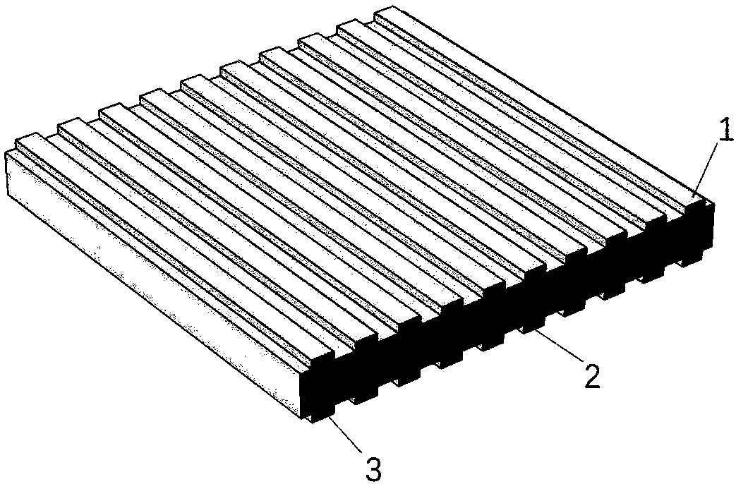
[0035] Figure 1~2Shown is a schematic diagram of the structure of a traditional aluminum nitride Lamb wave resonator. As shown in the figure, a certain number of top interdigital electrodes 1 and bottom interdigital electrodes 3 are arranged above and below the piezoelectric layer 2 made of aluminum nitride. After the excitation voltage is applied to the top interdigitated electrode 1 and the bottom interdigitated electrode 3, a Lamb wave parallel to the electrode width direction will be generated in the piezoelectric layer 2, and the Lamb...


PUM


Abstract

A radio frequency resonator structure disclosed by the invention includes a piezoelectric layer, and a certain amount of top interdigital electrodes and bottom interdigital electrodes respectively configured on the upper and lower surfaces of the piezoelectric layer, wherein troughs along the length direction of the top interdigital electrodes are respectively disposed at the positions between adjacent top interdigital electrodes on the upper surface of the piezoelectric layer; and at the same time, troughs along the length direction of the bottom interdigital electrodes are respectively disposed at the positions between adjacent bottom interdigital electrodes on the lower surface of the piezoelectric layer. By disposing troughs along the length direction of the interdigital electrodes onthe piezoelectric layer between adjacent interdigital electrodes, the invention obviously eliminates the parasitic mode of the resonator and improves the electromechanical coupling factor of the resonator, and is easy to implement and low in implementation cost.

Description

technical field [0001] The invention relates to the technical field of resonators, in particular to a radio frequency resonator structure that can effectively reduce spurious modes and improve electromechanical coupling coefficients. Background technique [0002] MEMS sensor devices play an extremely important role in the field of wireless communication. Among them, surface acoustic wave resonator (Surface Acoustic Wave Resonator) and bulk acoustic wave resonator (Bulk Acoustic Wave Resonator) occupy a dominant position in the mainstream market by virtue of their unique advantages. The surface acoustic wave resonator has a simple process and mature production, but due to the reflection grid in its own structure, it is relatively bulky and cannot be compatible with the IC process, which is not conducive to the development of miniaturization. Bulk acoustic wave resonators occupy a dominant position in the high-frequency field due to their excellent performance, but their reso...

Claims


Application Information

Patent Timeline
Patent Type & Authority Applications(China)
IPC IPC(8): H03H9/24H03H9/02H03H9/125
CPCH03H9/02244H03H9/02448H03H9/125H03H9/2405
Inventor 周杰孙成亮邹杨蔡耀唐楚滢
Owner 武汉敏声新技术有限公司
Learn More