Permanent magnet synchronous motor drive control real-time voltage regulating circuit based on silicon carbide/gallium nitride MOSFET

A technology of permanent magnet synchronous motor and voltage regulating circuit, which is applied in the direction of motor generator control, AC motor control, electronic commutation motor control, etc., and can solve the problem of low conversion efficiency, large heat generation of linear power amplifier, and limitation of motor drive control system Power level and other issues, achieve high conversion efficiency, solve the effect of large power amplifier loss and small loss

Active Publication Date: 2018-09-14
BEIHANG UNIV
View PDF6 Cites 3 Cited by
  • Summary
  • Abstract
  • Description
  • Claims
  • Application Information

AI Technical Summary

Problems solved by technology

[0005] However, the linear power amplifier itself has a large heat generation and low conversion efficiency, which severely limits the power level used in motor drive control systems, and is generally only used in low-power applications

Method used


Image

  • Permanent magnet synchronous motor drive control real-time voltage regulating circuit based on silicon carbide/gallium nitride MOSFET
  • Permanent magnet synchronous motor drive control real-time voltage regulating circuit based on silicon carbide/gallium nitride MOSFET
  • Permanent magnet synchronous motor drive control real-time voltage regulating circuit based on silicon carbide/gallium nitride MOSFET

Examples


Embodiment Construction

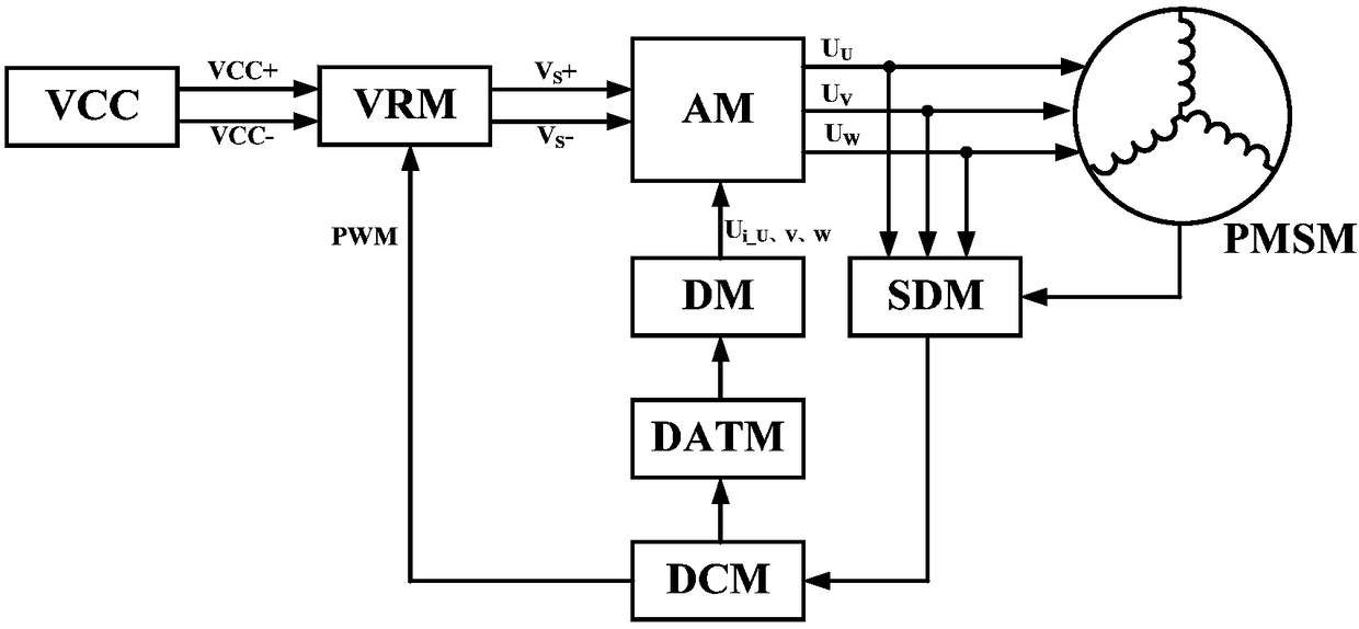
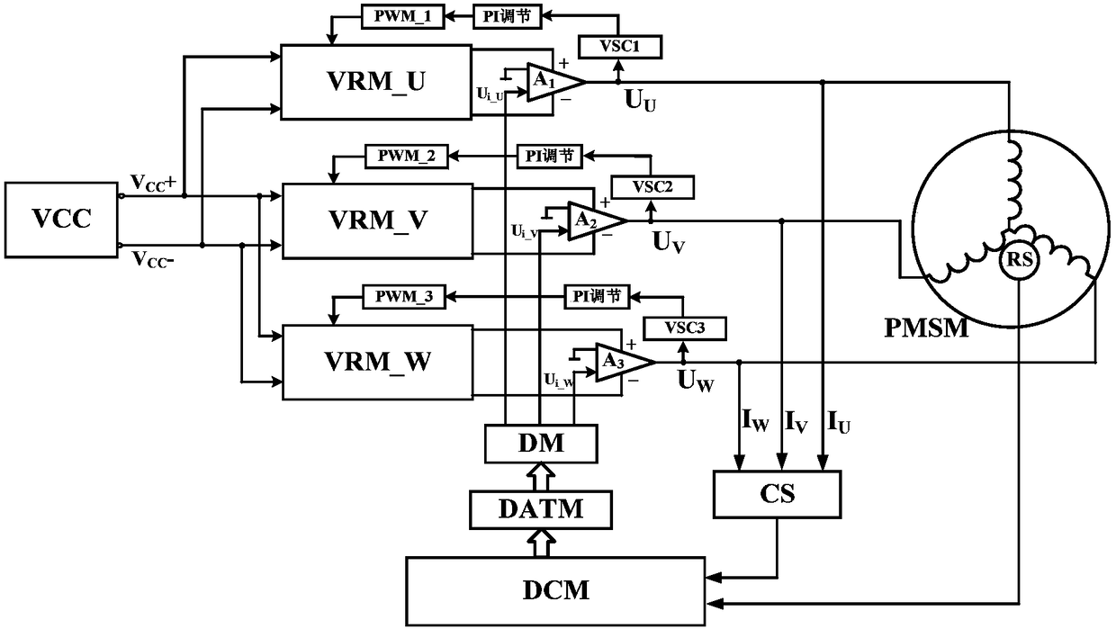
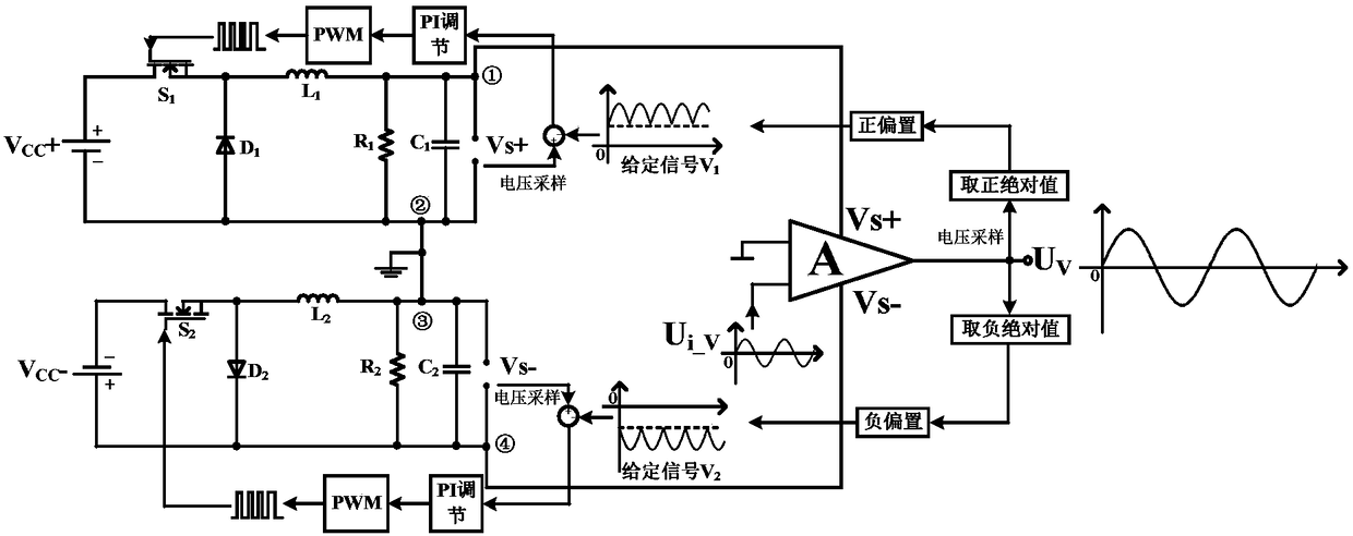
[0023] The implementation of the present invention will be further described below in conjunction with the accompanying drawings. see Figure 1-Figure 4 , the overall structural block diagram of the circuit is attached figure 2 As shown, it includes five parts: power amplifier power supply real-time voltage regulation module (VRM), power amplifier driver module (PAM), digital control module (DCM), signal detection processing module (SDM), and D / A conversion module (DATM).

[0024] Among them, the DSP adopts the 32-bit floating-point high-speed DSP TMS320F28335 of the Texas company in the United States, which has a high-speed processing capability of 150MHz and a 32-bit floating-point processing unit with high precision, low cost, low power consumption, high performance, and high peripheral integration. , a large amount of data and program storage; the switching device uses the CAS300M12BM2 silicon carbide MOSFET of the American CREE company, which has the advantages of fast ...


PUM


Abstract

The invention relates to a permanent magnet synchronous motor drive control real-time voltage regulating circuit based on a silicon carbide / gallium nitride MOSFET. The permanent magnet synchronous motor drive control real-time voltage regulating circuit based on a silicon carbide / gallium nitride MOSFET includes a power amplification power supply real-time voltage regulating module, a power amplification driving module, a digital control module, a signal detection processing module, and a D / A conversion module, wherein the power amplification power supply real-time voltage regulating module includes a positive and negative voltage stabilization DC power supply, a bipolar BUCK chopper circuit taking a silicon carbide / gallium nitride MOSFET as a switching device, and a voltage sampling circuit; and the power amplification driving module includes a high power linear power amplifier and an isolation module. The permanent magnet synchronous motor drive control real-time voltage regulating circuit based on a silicon carbide / gallium nitride MOSFET utilizes the advantages of the wide band gap power device silicon carbide / gallium nitride MOSFET that the switching speed is high and the loss is low and the like to overcome the problems that large power operation amplifier has large loss and low efficiency, thus being able to solve the problems that in a pulse width modulation driving mode,the high-frequency switching action causes current harmonics, motor torque jittering and instability under low speed and light load, and also being able to solve the problem of only applying to a small power occasion because of restriction of loss of the power amplifier, when the power amplifier is used for driving control of the permanent magnet synchronous motor.

Description

technical field [0001] The invention belongs to the technical field of motor automatic control, and specifically relates to a power amplifier power supply real-time voltage regulation circuit based on a wide bandgap power device silicon carbide / gallium nitride MOSFET, and more specifically relates to a permanent magnet synchronous motor drive control real-time voltage regulation circuit . Background technique [0002] There are two main implementations of high-precision permanent magnet synchronous motor drive control: pulse width modulation and linear power amplification. At present, the drive control method of pulse width modulation has been widely used in the drive control of permanent magnet synchronous motors because of its advantages such as low power loss, high efficiency, and easy realization of full digital control. [0003] However, in the drive control mode of pulse width modulation, the high-frequency modulation switching action will produce serious electromagne...

Claims


Application Information

Patent Timeline
IPC IPC(8): H02P21/00H02P27/06
CPCH02P21/0003H02P27/06
Inventor 丁晓峰成家伟郭宏
Owner BEIHANG UNIV
Why Eureka
Try Eureka