PIN needle material strip

A technology of strips and sidebands, which is applied in the manufacture of contacts, contact parts, electrical components, etc., can solve the problems of increasing the processing and manufacturing costs of electronic devices, difficult winding operations, and high labor intensity, so as to reduce the cutting process , Reduce the plating area and improve the processing efficiency

Pending Publication Date: 2018-09-14
DEYANG ZHIDA PRECISION ELECTRONICS
View PDF4 Cites 3 Cited by
  • Summary
  • Abstract
  • Description
  • Claims
  • Application Information

AI Technical Summary

Problems solved by technology

[0003] The technical problem to be solved and the technical task proposed by the present invention are to improve the existing technology and provide a PIN needle strip, which solves the problem of large material loss, difficult winding operation and high labor intensity of the PIN needle strip in the current technology. , increasing the processing cost of electronic devices

Method used


Image

  • PIN needle material strip
  • PIN needle material strip
  • PIN needle material strip

Examples


Embodiment Construction

[0024] The following will clearly and completely describe the technical solutions in the embodiments of the present invention with reference to the accompanying drawings in the embodiments of the present invention. Obviously, the described embodiments are only some, not all, embodiments of the present invention. Based on the embodiments of the present invention, all other embodiments obtained by persons of ordinary skill in the art without making creative efforts belong to the protection scope of the present invention.

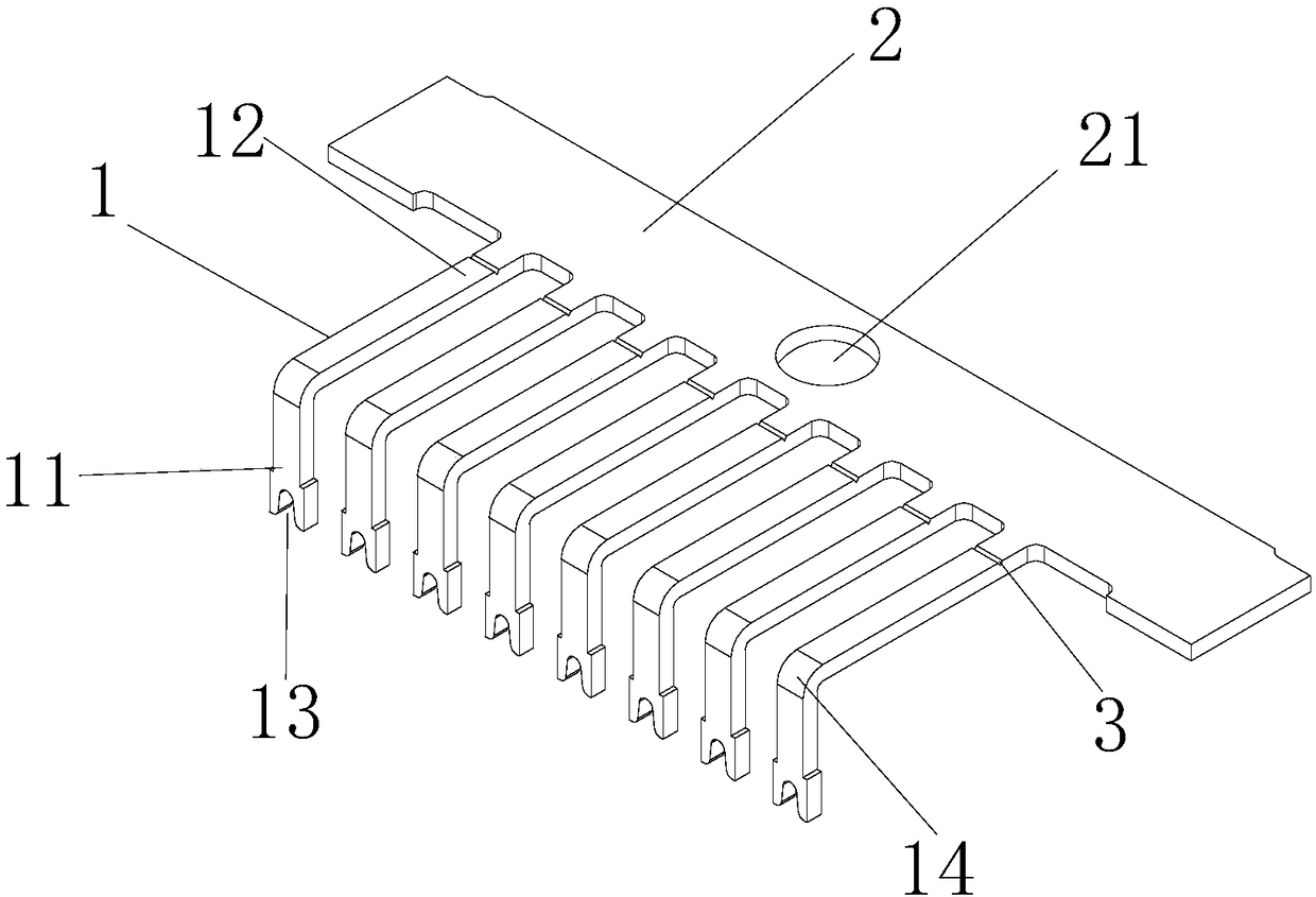
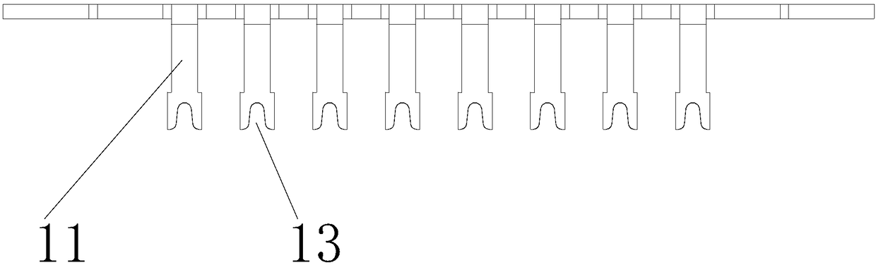
[0025] A PIN pin material tape disclosed in the embodiment of the present invention can reduce the width of the material tape, reduce the structure that needs to be cut off when assembling the PIN pin for connection, effectively reduce material loss, reduce processing cost, and reduce wiring difficulty , Improve the processing efficiency of assembling PIN pins.

[0026] Such as figure 1 and figure 2 As shown, a PIN needle strip includes a PIN needle 1 and a...


PUM


Abstract

The present invention discloses a PIN needle material strip. The PIN needle material strap comprises a PIN needle and a side strip, there is one side strip, the PIN needle is a stripe-shaped structure, one end of the PIN needle is a wiring pin, the other end of the PIN needle is a welding pin, a plurality of PIN needles are connected with the edge of the side strip through one end of the welding pin, and the top ends of the wiring pins of the PIN needles directly form insertion wire grooves for wiring. The PIN needle material strip employs the structure of the PIN needles being connected withthe single side strip, and the wiring pins of the PIN needles directly form the insertion wire grooves to change the wiring mode so as to effectively reduce the wiring efficiency, improve the wiring efficiency, reduce the cutting processing process, effectively improve the processing efficiency, reduce the electroplating area, reduce the material loss caused by cutting, reduce the whole width of the PIN needle material strip, reduce the width of the costumed metal strip and effectively reduce the cost of manufacturing the PIN needle material strip.

Description

technical field [0001] The invention relates to the technical field of electrical connectors, in particular to a PIN needle strip. Background technique [0002] The PIN pin is the connection between the internal circuit of the electronic device and the peripheral circuit, and the soldering pin of the PIN pin is connected to the pad on the printed board by soldering. At present, when manufacturing electronic devices, PIN needles are processed separately. The method is to punch out the required PIN needle structure with strip-shaped conductive metal materials. For the convenience of transportation and subsequent production, some residual materials are generally retained during stamping. , so that these PIN needles can be connected to each other, and the existing PIN needle strips mainly adopt the method of setting the PIN needles between two side strips. In the traditional PIN needle tape, after removing the side tape at one end of the PIN needle, this end becomes the winding...

Claims


Application Information

Patent Timeline
Patent Type & Authority Applications(China)
IPC IPC(8): H01R13/02H01R43/16H01F27/29
CPCH01R13/02H01R43/16H01F27/292
Inventor 杜效白阳东旭
Owner DEYANG ZHIDA PRECISION ELECTRONICS
Why Eureka
Try Eureka