
Loading gate with force eliminating and silt removing functions for hydraulic engineering

A hydraulic engineering and functional technology, applied in hydraulic engineering, marine engineering, coastline protection, etc., can solve the problems of reduced sealing performance of loading gates, failure of normal closing of loading gates, uneven force of loading gates, etc., so as to avoid the reduction of sealing performance. , avoid deformation, clear effect is good

Inactive Publication Date: 2018-09-14
SHENZHEN ANSIKE ELECTRONICS TECH CO LTD
View PDF1 Cites 5 Cited by
  • Summary
  • Abstract
  • Description
  • Claims
  • Application Information

AI Technical Summary

Problems solved by technology

[0003] However, due to the change of water volume in the river, undercurrents are easily generated in the water flow, and the undercurrents will make the force of the existing loading gates uneven, and easily cause the deformation of the existing loading gates, thus making the sealing of the existing loading gates difficult. Reduced performance, not only that, the water flow will carry a lot of silt and garbage which will accumulate at the bottom of the existing loading gate, when the existing loading gate is open, will accumulate at the bottom of the existing loading gate Sediment and garbage will block the limit slot of the existing loading gate, and the clogging of the limit slot of the existing loading gate will make the existing loading gate unable to close normally

Method used


Image

  • Loading gate with force eliminating and silt removing functions for hydraulic engineering
  • Loading gate with force eliminating and silt removing functions for hydraulic engineering
  • Loading gate with force eliminating and silt removing functions for hydraulic engineering

Examples


Embodiment Construction

[0031] The present invention is described in further detail now in conjunction with accompanying drawing. These drawings are all simplified schematic diagrams, which only illustrate the basic structure of the present invention in a schematic manner, so they only show the configurations related to the present invention.

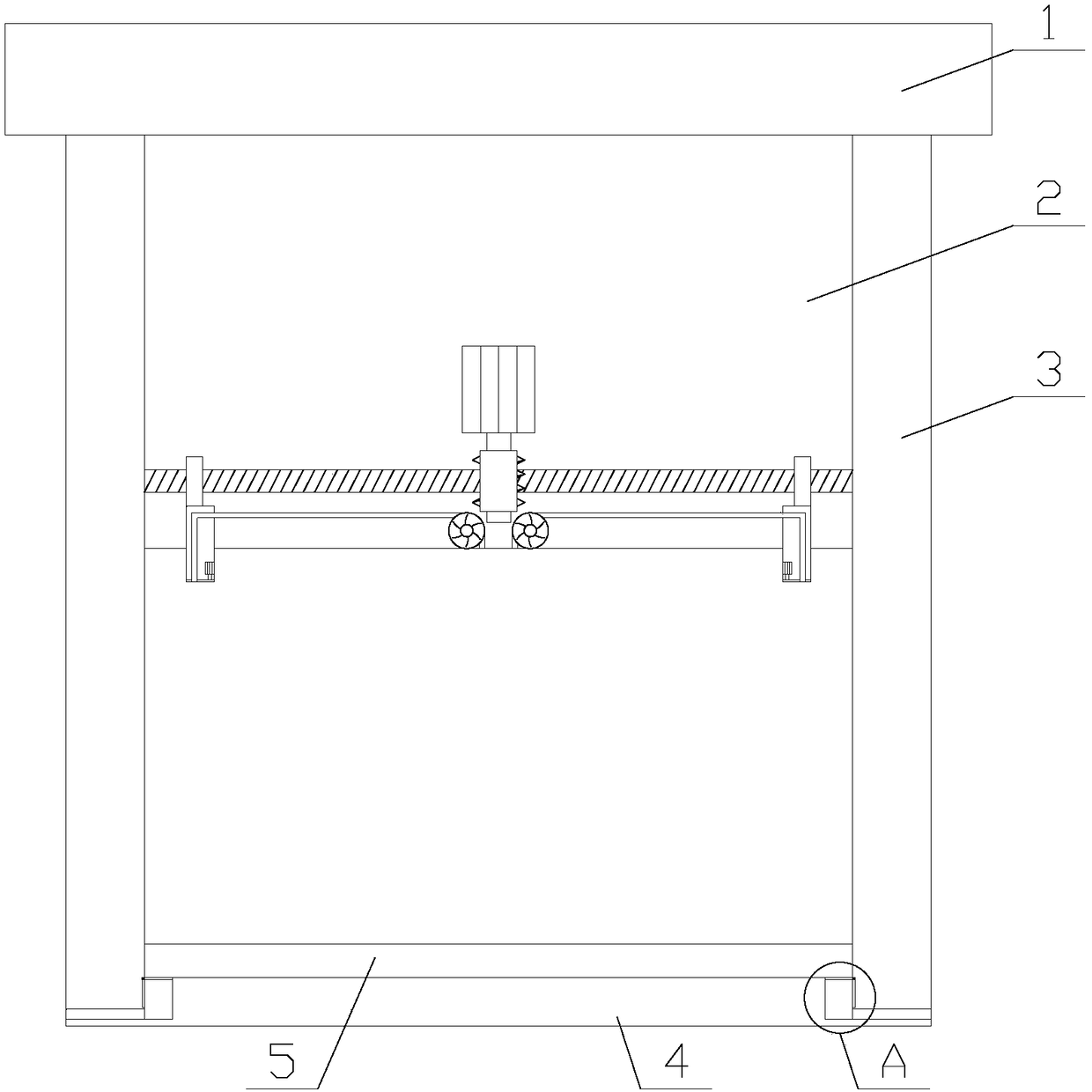
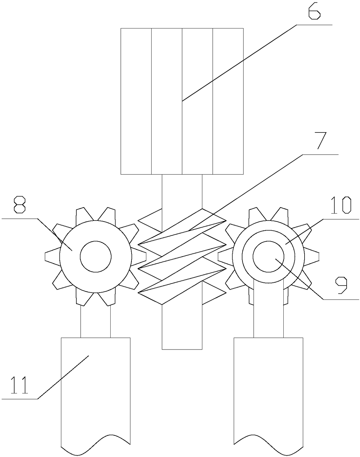
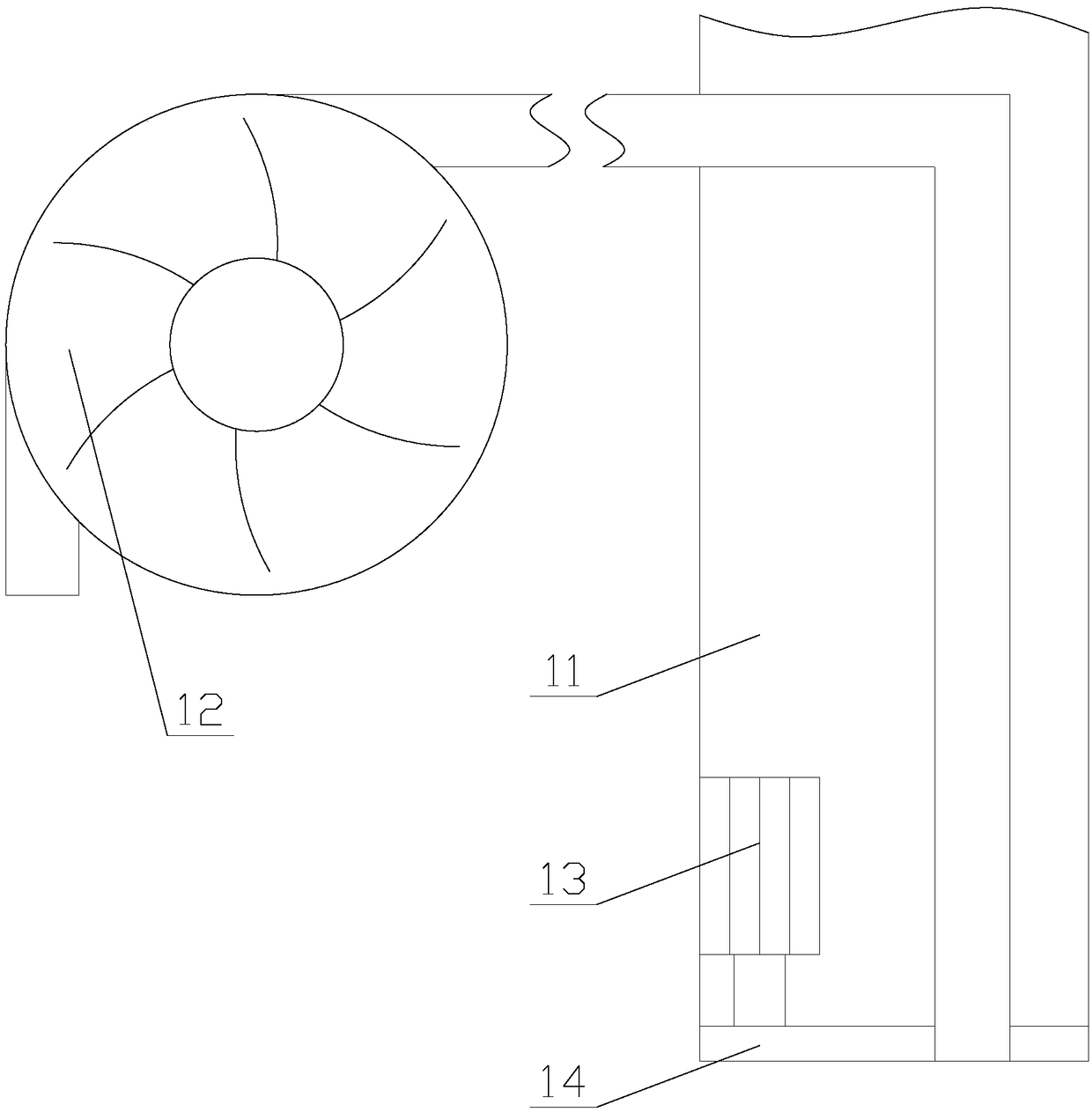
[0032] Such as figure 1 As shown, a loading gate with stilling and dredging functions for water conservancy projects includes a beam 1, a door leaf 2, a limit column 4 and two support columns 3, and a drive mechanism is provided inside the beam 1, The driving mechanism is connected to the door leaf 2 by transmission, and the two support columns 3 are respectively fixed on both sides below the beam 1, and the door leaf 2 and the limit column 4 are both arranged between the two support columns 3. Both ends of the limiting column 4 are respectively fixedly connected with two support columns 3, and the limiting column 4 is provided with a limiting groove 5 and tw...


PUM


Abstract

The invention relates to a loading gate with force eliminating and silt removing functions for hydraulic engineering. The loading gate comprises a beam, a gate flap, a limiting column and two supporting columns, wherein a driving mechanism is arranged in the beam; a scraping mechanism is arranged in the gate flap; a plurality of buffer gears are arranged between the gate flap and the supporting columns; the scraping mechanism comprises a first motor, a worm and two moving units; a clearing mechanism comprises a swing plate, a groove, a fixed shaft and a movable trough; the buffer gears comprise first chutes and third chutes. According to the loading gate with force eliminating and silt removing functions for hydraulic engineering, silts and wastes stacked in the limiting groove at the bottom of the loading gate can be removed by the scraping mechanism and the clearing mechanism, and the condition that the loading gate cannot be normally closed due to the silts and wastes is avoided. Moreover, due to the buffer gears, impact force of underflow to the gate flap can be reduced by the loading gate, and the condition that the gate flap deforms due to non-uniform stress at each position,so that the sealing performance of the loading gate is prevented from being reduced.

Description

technical field [0001] The invention relates to the field of water conservancy engineering equipment, in particular to a loading gate used in water conservancy projects with the functions of stilling force and dredging. Background technique [0002] Water conservancy engineering is a project built to control and allocate natural surface water and groundwater to achieve the purpose of eliminating harm and rejuvenating profits, while loading gates are low-head hydraulic structures built on rivers and channels to control flow and adjust water levels. Closing the loading gate can block floods, block tides or raise the upstream water level to meet the needs of irrigation, power generation, shipping, aquatic products, environmental protection, industrial and domestic water; opening the loading gate can vent flood, waterlogging, abandoned water or waste water, It can also supply water to downstream channels or channels. [0003] However, due to the change of water volume in the ri...

Claims


Application Information

Patent Timeline
Patent Type & Authority Applications(China)
IPC IPC(8): E02B7/20E02B8/02E02B8/06
Inventor 曹燕红
Owner SHENZHEN ANSIKE ELECTRONICS TECH CO LTD
Learn More