
Converter valve cooling system and cooling method

A cooling system, converter valve technology, applied in cooling/ventilation/heating transformation, output power conversion devices, electrical components, etc., can solve the problems of high energy consumption, large water consumption, environmental pollution, etc., to ensure cooling effect, energy saving, easy operation effect

Pending Publication Date: 2018-09-11
TBEA SUNOASIS
View PDF0 Cites 3 Cited by
  • Summary
  • Abstract
  • Description
  • Claims
  • Application Information

AI Technical Summary

Problems solved by technology

[0003] The cooling system of the converter valve in the existing direct current transmission has only two cooling methods: the air heat exchanger and the closed cooling tower. The air heat exchanger uses an external fan to transfer the heat to the atmosphere by convection. The higher the ambient temperature, the lower the efficiency. , not suitable for high-temperature environments; closed cooling towers use spray water as the heat transfer medium, and the spray water absorbs heat and turns into a gaseous state and then discharges it into the atmosphere. The heat exchange efficiency is high, but the water consumption is large, and the discharge contains scale and microorganisms Scaled sewage brings environmental pollution problems; there is another water-cooled unit that uses compressor refrigeration to provide chilled water at a lower temperature, but it cannot be used in large-capacity DC transmission cooling systems due to the disadvantage of too much energy consumption

Method used


Image

  • Converter valve cooling system and cooling method
  • Converter valve cooling system and cooling method

Examples


Embodiment Construction

[0029] The present invention will be described in detail below in conjunction with the accompanying drawings and specific embodiments.

[0030] In describing the present invention, it should be understood that the terms "center", "longitudinal", "transverse", "upper", "lower", "front", "rear", "left", "right", " The orientations or positional relationships indicated by "vertical", "horizontal", "top", "bottom", "inner" and "outer" are based on the orientations or positional relationships shown in the drawings, and are only for the convenience of describing the present invention and Simplified descriptions, rather than indicating or implying that the device or element referred to must have a particular orientation, be constructed and operate in a particular orientation, and thus should not be construed as limiting the invention. In addition, the terms "first" and "second" are used for descriptive purposes only, and cannot be interpreted as indicating or implying relative import...


PUM


Abstract

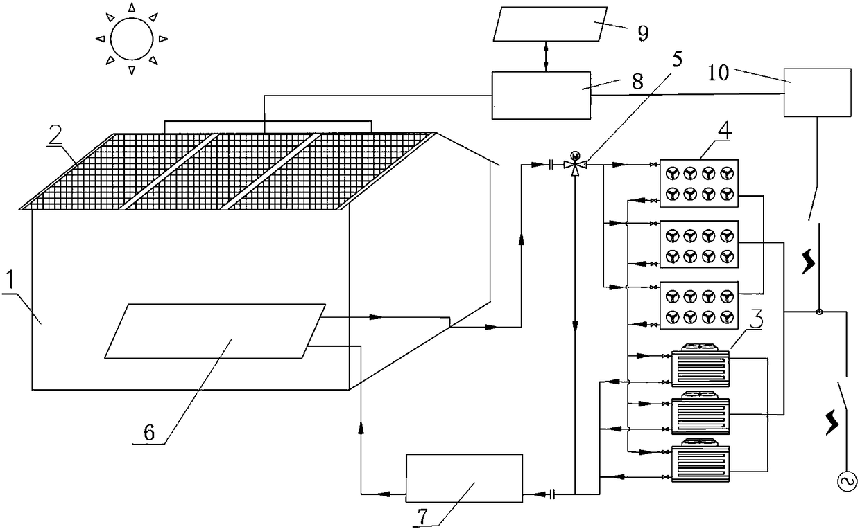
The invention discloses a converter valve cooling system and cooling method. The system comprises solar cell panels, a water cooling set, water-air heat exchangers and a three-way valve, the solar cell panels are connected with an input terminal of a solar energy power supply line through a luminous energy conversion device, an output terminal of the solar energy power supply line and a converterstation power supply system are both electrically connected with the water cooling set and the water-air heat exchangers, an outlet of a cooling medium pipeline of a converter valve is connected withan inlet of the three-way valve, a second outlet of the three-way valve is directly connected with an inlet of a water circulation host system through a pipeline, a first outlet of the three-way valveis connected with a medium inlet of the water cooling set, a medium outlet of the water cooling set is connected with the inlet of the water circulation host system, and an outlet of the water circulation host system is connected with a medium inlet of the converter valve. Power is supplied to heat exchange equipment of the cooling system through conversion of solar energy to electric energy, thedifficulty of high power consumption of the water cooling set with refrigeration through a compressor is solved by employing the solar energy power supply, effective energy saving and emission reduction can be realized, and the engineering application value is high.

Description

technical field [0001] The invention belongs to the technical field of direct current transmission, and in particular relates to an energy-saving and emission-reducing converter valve cooling system and a cooling method. Background technique [0002] The core equipment of DC transmission is the converter valve. The cooling system is the equipment that provides cooling for the power device of the converter valve. It is used to transfer the heat of the converter valve in the valve hall to the outdoor environment through the cooling medium to ensure the power device of the converter valve. Operating within a safe temperature, the cooling capacity of the cooling system is one of the key factors affecting the reliability of the converter valve. Reliability has always been the focus of cooling system design in the past. With the awareness of energy saving, emission reduction and environmental protection, the water and electricity loss of large-capacity DC transmission cooling syst...

Claims


Application Information

Patent Timeline
Patent Type & Authority Applications(China)
IPC IPC(8): H02M1/00H05K7/20
CPCH02M1/00H05K7/20327H05K7/20354H05K7/20381H05K7/20936H05K7/20945
Inventor 张长水林卫星盛俊毅田兴尚富鹏靳广超
Owner TBEA SUNOASIS
Learn More