Gear speed reducer capable of achieving flexible impact

A gear reduction and gear technology, applied in the field of transmission mechanism, can solve the problems of not being suitable for small machines or vehicles, increasing structural complexity, and generating large impacts, etc., and achieves the effects of simple structure, low manufacturing cost, and reduced impact

Pending Publication Date: 2018-09-11
CHANGAN UNIV
View PDF6 Cites 0 Cited by
  • Summary
  • Abstract
  • Description
  • Claims
  • Application Information

AI Technical Summary

Problems solved by technology

[0003] But at present, the traditional transmission mechanism adopts the method of toggling gears when shifting gears, that is, when switching gear sets, and realizes different transmissions by toggling the gears to different positions, which requires a clutch to cooperate when shifting gears. It plays a role, increasing the complexity of the structure, and in the process of toggling the gear, it will also produce a large impact and tooth beating.
Although the manual transmission for automobiles solves a large part of the impact problem, due to the existence of synchronizers, meshing sleeves and other structures, the structure is very complicated, and it is not suitable for small machinery or vehicles.

Method used


Image

  • Gear speed reducer capable of achieving flexible impact
  • Gear speed reducer capable of achieving flexible impact
  • Gear speed reducer capable of achieving flexible impact

Examples


Embodiment Construction

[0023] Below in conjunction with accompanying drawing, the present invention is described in further detail:

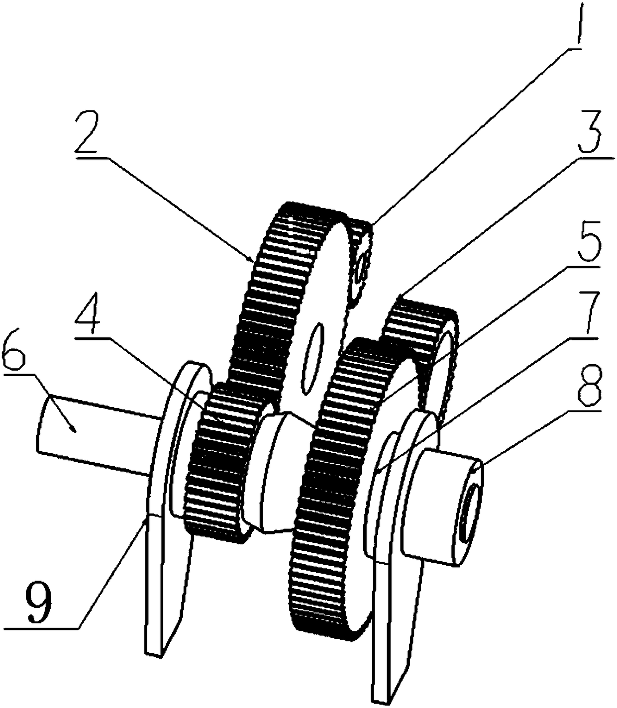
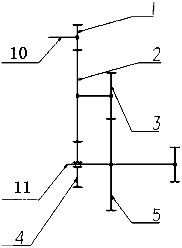
[0024] see figure 1 , Figure 3 to Figure 5 , a gear reduction device for realizing flexible impact, including a shift shaft 6 connected to two frames 9, the shift shaft 6 is located between the two frames 9 and is symmetrically provided with two tapered surfaces, And the side with the larger area of ​​the two conical surfaces is close together, and the third constant meshing gear 4 and the fourth constant meshing gear 5 are respectively arranged on the two conical surfaces, and the outer side of the conical surface and the fourth constant meshing gear The inner sides of the third constant meshing gear 4 and the fourth constant meshing gear 5 are provided with friction material coatings, and the third constant meshing gear 4 and the fourth constant meshing gear 5 are connected to the frame 9 on the corresponding side through the support flange 7 , The third constant...


PUM


Abstract

The invention discloses a gear speed reducer capable of achieving flexible impact. The device comprises a gear shifting shaft arranged on two racks, two conical faces are symmetrically arranged at theposition, between the two racks, of the gear shifting shaft, the sides, with the large area, of the two conical faces are tightly attached, the two conical faces are provided with a third constant mesh gear and a fourth constant mesh gear correspondingly, the third constant mesh gear and the fourth constant mesh gear are matched with the two conical faces, a first constant mesh gear is engaged with the third constant mesh gear, the first constant mesh gear is engaged with an input gear, a second constant mesh gear is engaged with the fourth constant mesh gear, the first constant mesh gear andthe second constant mesh gear are fixedly connected through a shaft, one free end of the gear shifting shaft serves as an output shaft, and an output wheel is connected to the output shaft. Disengaging and engaging of the gear shifting shaft and the gear are used for gear shifting, gear shifting in the motion can be achieved, the structure of a speed change mechanism is simplified, impact in thegear shifting process can be greatly reduced, and the defect of the traditional speed change mechanism can be effectively overcome.

Description

technical field [0001] The invention relates to a speed change mechanism, in particular to a gear reduction device for realizing flexible impact. Background technique [0002] In order to change the rotational speed and torque output by the engine, the gear transmission mechanism is widely used in various vehicles and machinery, and the output torque and rotational speed can be changed in fixed or stepwise manner by switching different gear sets. The application of the speed change mechanism can not only change the transmission ratio, meet the needs of traction under different driving conditions, make the prime mover work under favorable working conditions as much as possible, meet the possible output speed requirements, and change the size of the output speed and the output shaft in a wide range. The size of the upper torque can also meet the requirements of reverse driving, interruption of power, neutral gear operation, etc. [0003] But at present, the traditional transm...

Claims


Application Information

Patent Timeline
Patent Type & Authority Applications(China)
IPC IPC(8): F16H3/089F16H61/04
CPCF16H3/089F16H61/04
Inventor 叶敏迟明祥桑明徐振翔刘雯钦
Owner CHANGAN UNIV
Why Eureka
Try Eureka