
A two-dimensional configuration of multi-plate ejector and its application

A two-dimensional configuration and ejector technology, applied in jet pumps, machines/engines, non-displacement pumps, etc., can solve the problem of large flow loss of the ejected airflow, complex nozzle layout, affecting ejection performance, etc. problem, to achieve the effect of rapid hybrid development process, superior performance and low operating conditions

Active Publication Date: 2019-06-28
NAT UNIV OF DEFENSE TECH
View PDF9 Cites 0 Cited by
  • Summary
  • Abstract
  • Description
  • Claims
  • Application Information

AI Technical Summary

Problems solved by technology

The scheme of multi-nozzle ejector with axisymmetric configuration is: a plurality of "L" supersonic nozzles distributed along the circumferential direction are built into the circular channel, and a support structure is set between the nozzles to reduce vibration. This scheme has the advantages of Disadvantages of complex layout of the nozzle and large flow loss of the ejected airflow
In addition, the ejector airflow and the ejected airflow in the multi-nozzle ejector with axisymmetric configuration are unevenly distributed in the mixing chamber, which will cause a large shock wave loss and affect the ejection performance.

Method used


Image

  • A two-dimensional configuration of multi-plate ejector and its application
  • A two-dimensional configuration of multi-plate ejector and its application
  • A two-dimensional configuration of multi-plate ejector and its application

Examples


Embodiment 1

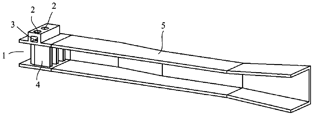
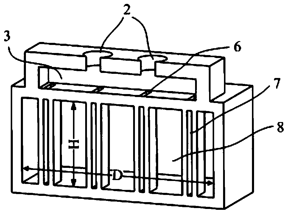
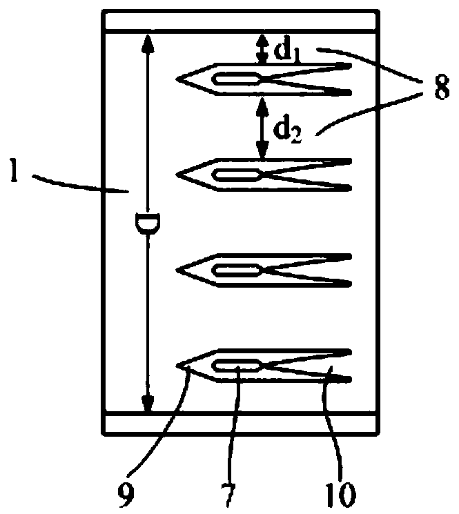
[0033]As shown in the accompanying drawings, the present invention proposes a multi-branch ejector with two-dimensional configuration. The opening at one end of the ejector is provided with an ejected air inlet 1 docked with the inner cavity of the ejector, and the shape and size of the ejected air inlet 1 are the same as the size of the inner rectangular cavity of the ejector. The opening at the other end is provided with a mixing diffuser pipe 5 that is docked with the inner cavity of the ejector, and a rectangular gas collection chamber 3 is provided on the upper side wall of the ejector, and the inner cavity of the ejector is provided with two Vertical support plate 4, the inside of the support plate 4 is provided with a vertical nozzle air guide cavity 7, the two ends of the support plate 4 are connected with the inner side wall of the ejector, on the side wall above the gas collection chamber 3 There is an ejection air inlet 2, and the gas collection chamber 3 and the no...

Embodiment 2

[0036] As shown in the accompanying drawings, the present invention proposes a multi-branch ejector with two-dimensional configuration. One end of the ejector is provided with an ejected air inlet 1 docked with the inner cavity of the ejector, and the shape and size of the ejected air inlet 2 is the same as the size of the inner rectangular cavity of the ejector, and the other end of the ejector is provided with There is a mixing diffuser pipe 5 docked with the inner cavity of the ejector, the shape and size of the end of the mixed diffuser pipe 5 docked with the ejector is the same as the size of the inner rectangular cavity of the ejector, and the upper side wall of the ejector and the lower side wall are respectively provided with a gas collection cavity 3, the inner cavity of the ejector is provided with four support plates 4, and the inside of the support plate 4 is provided with a vertical nozzle air guide cavity 7, above the ejector The upper side wall of the gas collec...


PUM


Abstract

The invention relates to a two-dimensional configuration multi-support plate ejector and application, belongs to the technical field of ejector application, and provides combination application of a two-dimensional configuration multi-support plate ejector and a two-dimensional mixed diffusion pipe. When the performance of the ejector pursues the small supercharge ratio and the large ejection coefficient, combination application of the two-dimensional configuration multi-support plate ejector and a rectangle uniform-section mixed diffusion pipe is used; and when the performance of the ejectorpursues the large supercharge ratio and the small ejection coefficient, combination application of the two-dimensional configuration multi-support plate ejector and a rectangle second-throat mixed diffusion pipe is used. By means of the application, contact areas between multiple ejecting airflow and ejected airflow which are even are large, and the mixing effect is good; and the flow field structure in the mixed diffusion pipe is even, and the shock wave loss is small. Based on the ejector applied in the invention has the advantages that the running working condition is low, and the performance is excellent.

Description

technical field [0001] The invention belongs to the technical field of ejector applications, and in particular relates to a two-dimensional multi-plate ejector and its application. Background technique [0002] An ejector is a gas machine that pressurizes a low total pressure airflow by means of a high total pressure airflow. Mechanistically, the ejector transmits the kinetic energy of the ejected airflow to the ejected airflow through the transport of turbulent flow in the mixed layer in contact between the ejected airflow and the ejected airflow to increase the total pressure of the ejected airflow. Effect. Therefore, enhancing the mixing between the ejected airflow and the ejected airflow is a main way to improve the performance of the ejector. There are two ways to enhance the mixing: increasing the mixing area between the ejected airflow and the ejected airflow, and designing the outlet of the special-shaped nozzle to enhance the disturbance between the two airflows. ...

Claims


Application Information

Patent Timeline
Patent Type & Authority Patents(China)
IPC IPC(8): F04F5/16F04F5/44
CPCF04F5/16F04F5/44
Inventor 徐万武叶伟李平张富强
Owner NAT UNIV OF DEFENSE TECH
Learn More