Oxidant mixed injection system and an operation method for underground coal gasification

An underground gasification and injection system technology, applied in coal gasification, underground mining, construction, etc., can solve the problem of limited operating temperature range in the selection and design of underground equipment, increased equipment transportation costs and delivery time, and the gasification process is not fully reached. problems such as optimal conditions, to achieve the effect of reducing size and cost, reducing material selection restrictions, and improving stable quality

Pending Publication Date: 2018-09-11
ZHONGWEI SHANGHAI ENERGY TECH CO LTD
View PDF0 Cites 0 Cited by
  • Summary
  • Abstract
  • Description
  • Claims
  • Application Information

AI Technical Summary

Problems solved by technology

[0015] 2) When multiple coiled tubing strings are used, the outer diameter of the coiled tubing bundle is relatively large, so larger coiled tubing reel equipment and a non-standard size wellhead control system are required, which will greatly increase the transportation cost of the equipment and delivery time
[0016] 3) When the coiled tubing is required to meet the application of pure oxygen, its material selection, component processing and cleaning all have certain special requirements to prevent the shock and spontaneous combustion of the pure oxygen working environment, which will increase the project cost to a certain extent
This largely limits the operating temperature range of ISC and the selection and design of downhole equipment
[0018] 5) Since the oxidant and water usually enter the combustion and gasification zone separately, the gasification process does not fully reach the optimal conditions

Method used


Image

  • Oxidant mixed injection system and an operation method for underground coal gasification
  • Oxidant mixed injection system and an operation method for underground coal gasification
  • Oxidant mixed injection system and an operation method for underground coal gasification

Examples


Embodiment Construction

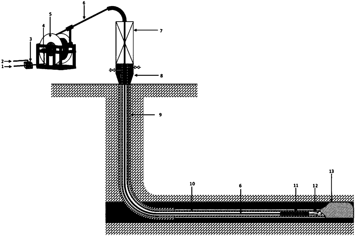
[0028] The invention provides an oxidant mixing injection system and an operation method for an underground coal gasification process. Specifically, the present invention provides an injection system for mixing oxidant and water in a controllable ratio in an underground coal gasification process, and also provides the application of this oxidant mixed injection system in an underground coal gasification process. The operation method, specifically, can be used in the normal operation process of the underground coal gasification process.

[0029] The invention provides an oxidant mixing injection system for an underground coal gasification process, which includes:

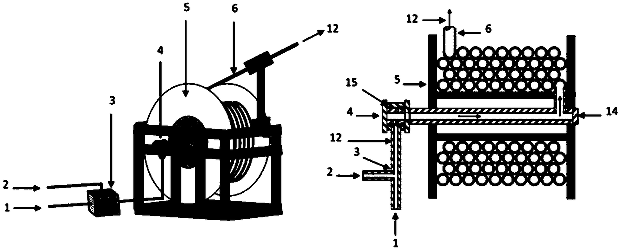
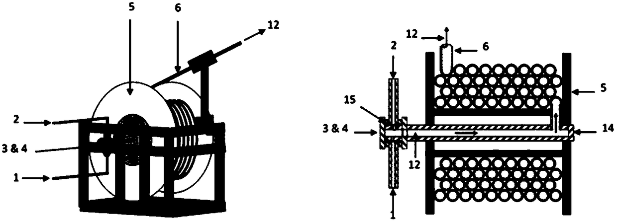
[0030] 1) Two-phase mixing equipment, located upstream of the rotary joint of the coiled tubing reel, is used to uniformly mix the oxidant and water at the surface.

[0031] 2) Rotary joint, located downstream of the two-phase mixing equipment, connects the two-phase flow with the coiled tubing string through the ce...


PUM


Abstract

The invention provides an oxidant mixed injection system and an operation method for an underground coal gasification (ISC). The system includes the following components: 1) two-phase mixing equipment; 2) a rotary joint; 3) a coiled tubing reel and a coiled tubing string. The coiled tubing string is wound on the coiled tubing reel. The coiled tubing reel is wound and retracted by the coiled tubingin the working state, and the coiled tubing string serves as a two-phase flow conveying passage. A predetermined position for transporting oxidant and water and transferring the downhole nozzle to the underground coal seam; 4) a deflector; 5) a downhole nozzle device located downstream of the deflector for injecting the two-phase mist stream into the gasification zone of the underground gasifier.The injection liner is used as a conveying and operation passage for the coiled tubing string and the downhole equipment, and a distributed temperature, pressure and acoustic wave sensor is fixedly disposed outside the injection liner. The system is used to monitor the temperature of the combustion and gasification zone and the pressure of the coal underground gasification reaction zone.

Description

technical field [0001] The invention provides an oxidant mixing injection system and an operation method used in an underground coal gasification process (ISC). In particular, the present invention provides an injection system for mixing oxidant and water in a controllable ratio in an underground coal gasification process, and also provides the operation of this oxidant mixed injection system in an underground coal gasification process The method can be specifically used in the normal operation process of the underground coal gasification process. Background technique [0002] Underground Coal Gasification (ISC) is the process of converting coal directly into a product gas, commonly referred to as synthesis gas, through the combustion and gasification reactions of underground coal seams in the presence of oxidants, which can then be used in a variety of applications feedstocks, including fuel production, chemical production and power generation. This underground coal gasif...

Claims


Application Information

Patent Timeline
IPC IPC(8): E21B43/295
CPCE21B43/295
Inventor 道格·雅各布斯闵振华卡斯珀·扬·亨德利克·伯格汪原理
Owner ZHONGWEI SHANGHAI ENERGY TECH CO LTD
Why Eureka
Try Eureka