
Integral beam-end retractable device suitable for super-long-span railway steel bridge

A telescopic device, integral technology, applied in the direction of bridges, bridge parts, bridge construction, etc., can solve the problems of skewed movable steel sleepers, cracked or broken connecting rods, difficult error control, etc., and achieves high vertical stiffness and good integrity. , the effect of reducing the design workload

Pending Publication Date: 2018-09-11
RAILWAY ENG RES INST CHINA ACADEMY OF RAILWAY SCI +2
View PDF3 Cites 9 Cited by
  • Summary
  • Abstract
  • Description
  • Claims
  • Application Information

AI Technical Summary

Problems solved by technology

The patent No. ZL201520771388.5 is a railway bridge beam end telescopic device. This patent proposes a bottom-loaded beam end telescopic device with a supporting beam placed below the left and right rails of the railway with an I-shaped cross section. The modular design can realize the maximum design expansion and contraction displacement of ±1200mm under the condition of 5 movable steel sleepers. Analyzing the structure diagram given by the patent and combining the field engineering application practice, it can be seen that there are the following problems and shortcomings: (1) For single-line For the support beam and displacement box structure where the left and right rails are separated, due to the difficulty in controlling the errors during on-site construction and installation, there may be large deviations in the parallelism of the displacement box at the lower part of the left and right rails and the degree of coincidence with the center line of the line. In the subsequent use process, with the longitudinal reciprocating large displacement and lateral displacement, the movable steel sleeper of the telescopic device may be easily skewed, and the connecting rod may be easily cracked or broken due to the influence of uneven force on the left and right sides or difference in lateral displacement. question
The lateral displacement of the displacement box will be directly transmitted to the upper rail through the steel sleeper, resulting in a bad geometric state of the rail, affecting the stability and even safety of driving, requiring frequent maintenance and repair by the on-site engineering department
Due to the short period of maintenance and repair of high-speed railway skylights, generally only about 3 to 4 hours, it brings great difficulties to the daily maintenance and repair of the site after the disease occurs

Method used


Image

  • Integral beam-end retractable device suitable for super-long-span railway steel bridge
  • Integral beam-end retractable device suitable for super-long-span railway steel bridge
  • Integral beam-end retractable device suitable for super-long-span railway steel bridge

Examples


Embodiment approach

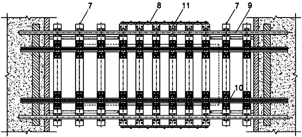
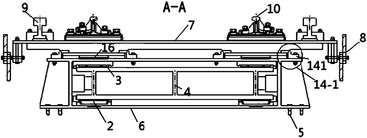
[0044] refer to Figure 3a~3c and Figures 5a-5c , the fixed steel sleeper 7 on the movable end displacement box 1 is fixedly connected with the movable end displacement box 1 through the first fixed steel sleeper connection gusset 141 to realize the synchronization of displacement. Such as Figure 5a As shown, a gap may be provided between the first fixed steel sleeper connecting buckle plate 141 and the vertical contact surface (at F) of the fixed steel sleeper 7, the gap is determined according to the lateral displacement of the main bridge end, and the gap is filled with Materials with high modulus of elasticity. The fixed steel sleeper connects the buckle plate and the movable end displacement box, and the fixed steel sleeper 7 on the fixed end displacement box 6 is connected with the fixed end displacement box 6 through the second fixed steel sleeper connection buckle plate 142, wherein as Figure 5c As shown, there is a gap between the second fixed steel sleeper conn...


PUM


Abstract

The invention relates to an integral beam-end retractable device suitable for a super-long-span railway steel bridge. The device comprises a basic support structure which is composed of a movable-enddisplacement box, a fixed-end displacement box and a support beam and arranged at the bottom of the beam-end retractable device, wherein the support beam is an integral box-type beam; the device further comprises a plurality of movable steel sleepers, a plurality of fixed steel sleepers, two steel rails and a connecting rod device, wherein the movable steel sleepers and the fixed steel sleepers are arranged in parallel. The retractable device can significantly improve the vertical support stiffness of a beam-end region rail, and open grooves of a main bridge beam end are reduced or even eliminated; meanwhile, the requirement of the beam end for freely extending and retracting in the axial direction of a bridge and displacing to a certain extent in the transverse direction of the bridge ismet at the same time, and a traditional set pattern that a beam-end retractable device and a steel-rail retractable adjuster are designed separately is changed through an integrated design concept.

Description

technical field [0001] The invention relates to an integral beam end telescopic device suitable for a super-long-span railway steel bridge. Background technique [0002] The super-long-span railway steel bridge has a large temperature span, and the overall structural stiffness is low, and the geometric nonlinear effect is obvious. The location will produce very obvious spatial displacement, such as the longitudinal displacement may reach 2500mm and above, and the transverse bending angle of the beam end between the main bridge and the approach bridge will exceed 2.5‰rad. It is difficult for the existing railway beam end telescopic device to adapt to this The displacement value is reflected in the limited rigidity of the structure and the inability to resist the lateral displacement difference between the main approach bridges. Therefore, a beam end telescopic device with large vertical stiffness and good integrity is invented, which can better adapt to the lateral displacem...

Claims


Application Information

Patent Timeline
IPC IPC(8): E01D2/04E01D19/06E01B3/00E01B5/02
CPCE01B3/00E01B5/02E01D2/04E01D19/06Y02A30/30
Inventor 郭辉赵欣欣刘晓光胡所亭苏朋飞王丽臧晓秋
Owner RAILWAY ENG RES INST CHINA ACADEMY OF RAILWAY SCI
Learn More