
Reinforcing method of fire-damaged bridge

A fire-burning and bridge technology, applied in bridge reinforcement, bridges, bridge materials, etc., can solve the problems of affecting the speed of operation, affecting the bearing capacity, weakening the bending stiffness of beams, etc., to solve the problem of vertical stiffness and transverse integrity, and improve the vertical Effects on stiffness and integrity, restoration of operational load-carrying capacity

Active Publication Date: 2016-12-14
NINGBO COMM PLANNING INST CO LTD +1
View PDF6 Cites 6 Cited by
  • Summary
  • Abstract
  • Description
  • Claims
  • Application Information

AI Technical Summary

Problems solved by technology

This method can indeed play a role in strengthening in theory, but the applicant found that in the actual use process, on the one hand, because the steel plate only covers the overheated bottom plate and part of the web, the load will gradually concentrate in the subsequent use process. The web where the steel plate is not covered poses a hidden danger to the structural safety of this part of the area; on the other hand, the steel plate is fixed by implanting steel bars into the beam body, which will weaken the bending stiffness of the beam and affect its bearing capacity
At the same time, dense concrete is used for filling, and the bonding performance between it and the original concrete and steel plate is insufficient, which can easily lead to falling off
Furthermore, the above-mentioned construction method requires the laying of supports, which is not only time-consuming, but also affects the speed of operation and traffic, and cannot be used in areas where there is a need for traffic under the bridge and other areas where it is difficult to erect supports.

Method used


Image

  • Reinforcing method of fire-damaged bridge
  • Reinforcing method of fire-damaged bridge
  • Reinforcing method of fire-damaged bridge

Examples


Embodiment Construction

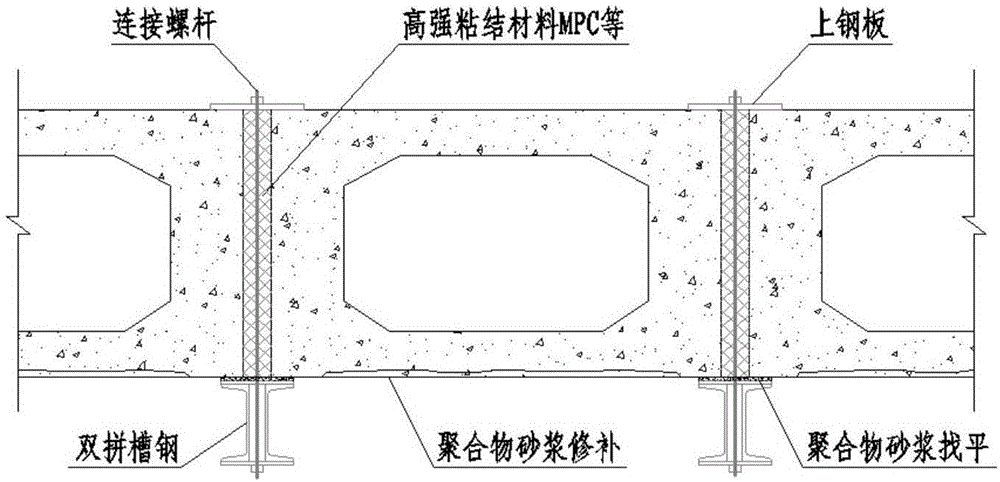
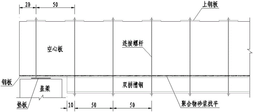
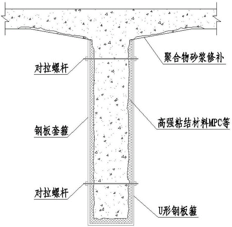
[0040] The present invention will be further elaborated and illustrated below in conjunction with the accompanying drawings and specific embodiments. This specific embodiment provides a preferred reinforcement method for fire-damaged bridges. However, the following technical features can be combined accordingly on the premise that there is no conflict with each other.

[0041] In this embodiment, the bridge to be reinforced is formed by erecting hollow slab girders, T girders or small box girders. The lower part of the bridge was burned, causing the bottom plate of the hollow slab girder or the web, bottom plate and top plate of the T-beam or small box girder to be damaged to varying degrees. Adopt reinforcement method of the present invention to reinforce it, specifically as follows:

[0042] 1. Assess the degree of component damage

[0043] First of all, according to the relevant provisions of the "Building Structure Appraisal Standard after Fire", the damage of the fire-...


PUM

PropertyMeasurementUnit
Bond strengthaaaaaaaaaa
Plate thicknessaaaaaaaaaa
Diameteraaaaaaaaaa

Abstract

The invention discloses a reinforcing method of a fire-damaged bridge, and belongs to the field of construction methods. The reinforcing method comprises the following steps of for a fire-damaged hollow slab beam or T-shaped beam or small box girder of the bridge, chiseling the loose and fallen concrete at the lower surface of the fire-damaged hollow slab beam or T-shaped beam or small box girder by an artificial chiseling method, and flushing and clearing the concrete at the lower surface of the beam slab by a high-pressure water launce; lifting a steel plate or a steel beam, casting a high-strength adhering material, and reinforcing the damaged part. The reinforcing method has the advantages that the vertical rigidity and integrity of the fire-damaged bridge can be greatly improved, and the operation and carrying capacity of the bridge can be restored as soon as possible; by adopting the bracket-free reinforcing construction method, the problem of insufficient vertical rigidity and transverse integrity of the bridge is solved, and the problem of failure to erect the bracket under the bridge or higher erection cost of the bracket is solved; the consuming time of reinforcing procedure is short, the construction is convenient, and the like.

Description

technical field [0001] The invention belongs to the field of construction methods, and in particular relates to a method for reinforcing bridges damaged by fire. Background technique [0002] In recent years, China's highway and bridge construction has developed rapidly. The number of fires caused by combustible materials under highway bridges, especially bridges at the urban-rural junction, is difficult to control due to many influencing factors, and the number of fires is gradually increasing. The fire not only causes serious economic losses, but also the strength and elastic modulus of the reinforced concrete structure of the bridge will decrease under the physical and chemical action of the fire, and the bond strength between the steel bar and the concrete will decrease accordingly, and the cross-sectional load of the bridge will decrease. The force will also be reduced, causing bridge safety hazards and affecting road operation safety. Therefore, it is necessary to qui...

Claims


Application Information

Patent Timeline
IPC IPC(8): E01D22/00E01D101/30
CPCE01D22/00E01D2101/30
Inventor 朱汉华陈孟冲李志勇
Owner NINGBO COMM PLANNING INST CO LTD
Learn More