Antenna system and communication terminal
A technology of antenna system and system ground, which is applied in the direction of antenna grounding device, separately powered antenna array, antenna grounding switch structure connection, etc., can solve the problems of large band space loss, interruption, communication link interference, etc., and achieve large beam width , uniform beam width and strong communication signal
- Summary
- Abstract
- Description
- Claims
- Application Information
AI Technical Summary
Problems solved by technology
Method used
Image
Examples
Embodiment 1
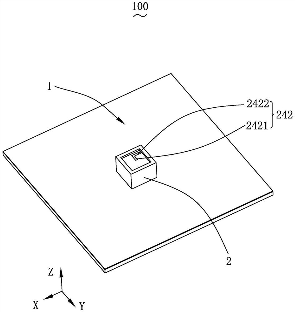
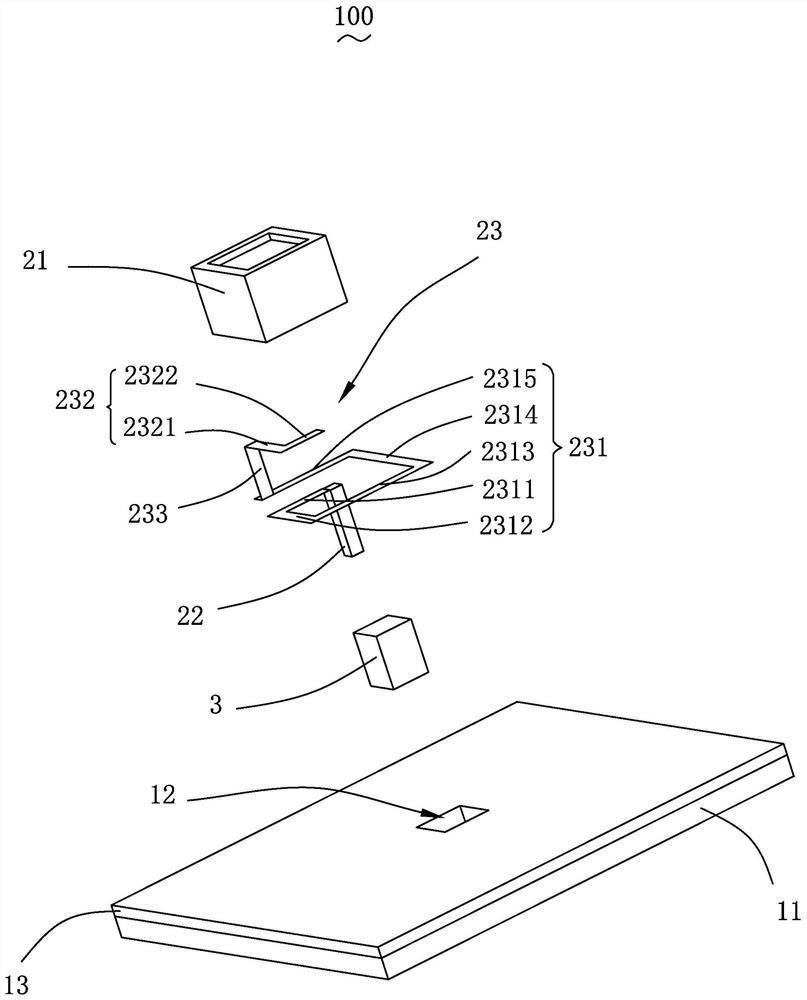
[0038] see Figure 1-2 , the present invention provides an antenna system 100, including a system ground unit 1 and an antenna unit 2 coupled to each other.
[0039] The system ground unit 1 includes a substrate 11 and a system ground 13 laid on the surface of the substrate 11 .
[0040] The antenna unit 2 includes a support frame 21 , a monopole feeding pin 22 and a monopole radiator 23 .
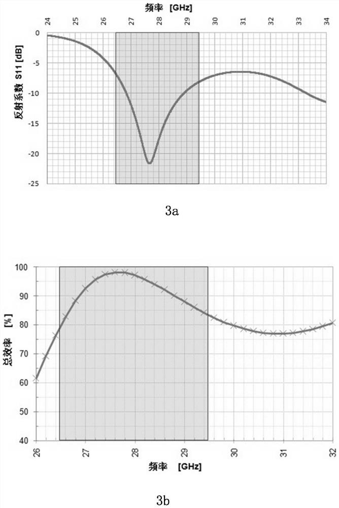
[0041] In this implementation manner, the antenna unit is a millimeter wave antenna, and its operating frequency range is 26.5 GHz˜29.5 GHz.
[0042] The supporting frame 21 has a receiving space, which is a columnar structure with one end open and one end closed, such as a rectangular column. An open end cover of the support frame 21 is fixed to the system unit 1 .
[0043] In this embodiment, the size of the supporting frame 21 is 2.8mm*2.8mm*2mm, but of course it is not limited thereto.
[0044] The support frame 21 is specifically made of low temperature co-fired ceramics (Low Temp...
Embodiment 2
[0060] Please combine Figure 5 As shown, this embodiment is basically the same as Embodiment 1, except that the antenna system 500 includes several antenna units 52 arranged in a linear array, for example, includes at least three antenna units 52 arranged in a linear array Except for the system unit 51, other structures are the same as those in Embodiment 1, and will not be repeated here.
[0061] This embodiment is described by taking three antenna units 52 as an example, and the three antenna units 52 form a phased array antenna.
[0062] Please combine Figure 6-7 as shown, Figure 6 is the rectangular coordinate diagram and polar coordinate diagram of the gain of the antenna system at 28GHz, where Figure 6 a is the rectangular coordinate diagram on the surface of Phi=0°, Figure 6 b is the polar coordinate diagram on the Phi=0° plane.
[0063] Figure 6 The antenna gain at different scanning angles is shown, and it can be seen that the main lobe of the antenna beam...
Embodiment 3
[0066] Please combine Figure 8 As shown, this embodiment is basically the same as Embodiment 1, except that the antenna system 800 includes several antenna units 82 arranged in a planar array, such as including at least four antenna units 82 arranged in a rectangular array on the unit 81 of the system. Except for this, other structures are the same as those in Embodiment 1, and will not be repeated here.
[0067] This embodiment is described by taking four antenna units 82 as an example, and the four antenna units 82 form a rectangular phased array antenna, that is, arranged in a 2*2 matrix. The antenna units 82 arranged in an array can perform beam forming and beam steering at different angles on any plane, that is, the beam steering is almost omnidirectional.
[0068] Please combine Figure 9-13 as shown, Figure 9 is the gain rectangular coordinate diagram and polar coordinate diagram of the antenna system 800 at a plane Phi=0° and a frequency of 28 GHz, Figure 9 a i...
PUM
 Abstract
Description
Claims
Application Information
 - Generate Ideas
- Intellectual Property
- Life Sciences
- Materials
- Tech Scout
- Unparalleled Data Quality
- Higher Quality Content
- 60% Fewer Hallucinations
Browse by: Latest US Patents, China's latest patents, Technical Efficacy Thesaurus, Application Domain, Technology Topic, Popular Technical Reports.
© 2025 PatSnap. All rights reserved.Legal|Privacy policy|Modern Slavery Act Transparency Statement|Sitemap|About US| Contact US: help@patsnap.com


