
Circularly polarized UHF RFID reader-writer antenna with easy impedance matching

An impedance matching and circular polarization technology, applied in the field of RFID antennas, can solve the problems of reducing the circular polarization bandwidth, narrow impedance matching bandwidth, narrow circular polarization bandwidth, etc., and achieve the effect of good input reactance matching and simple optimization steps.

Inactive Publication Date: 2018-09-07
CHONGQING UNIV OF POSTS & TELECOMM
View PDF3 Cites 4 Cited by
  • Summary
  • Abstract
  • Description
  • Claims
  • Application Information

AI Technical Summary

Problems solved by technology

For a circularly polarized microstrip antenna with coaxial feed, the coaxial feed probe will introduce inductive reactance. In order to ensure the circular polarization characteristics of the antenna, this inductive reactance cannot be canceled by the antenna radiation inductive reactance
Faced with the above problems in this subsection, some existing UHF RFID antennas do not deal with them, directly retaining the inductive reactance introduced by the coaxial feeding probe, which has the defect of narrow impedance matching bandwidth; some UHF RFID antennas choose to reduce the circular polarization bandwidth The way to offset part of the inductive reactance introduced by the coaxial feeding probe has the defect of narrow circular polarization bandwidth; and some UHF RFID antennas choose to add an additional impedance matching layer to achieve good impedance matching, which brings is the increase in the complexity of the antenna structure

Method used


Image

  • Circularly polarized UHF RFID reader-writer antenna with easy impedance matching
  • Circularly polarized UHF RFID reader-writer antenna with easy impedance matching
  • Circularly polarized UHF RFID reader-writer antenna with easy impedance matching

Examples


Embodiment Construction

[0026] The present invention will be further described below with reference to the accompanying drawings and examples. It should be noted that this embodiment is based on the technical solution, but the scope of protection of the present invention is not limited to this embodiment.

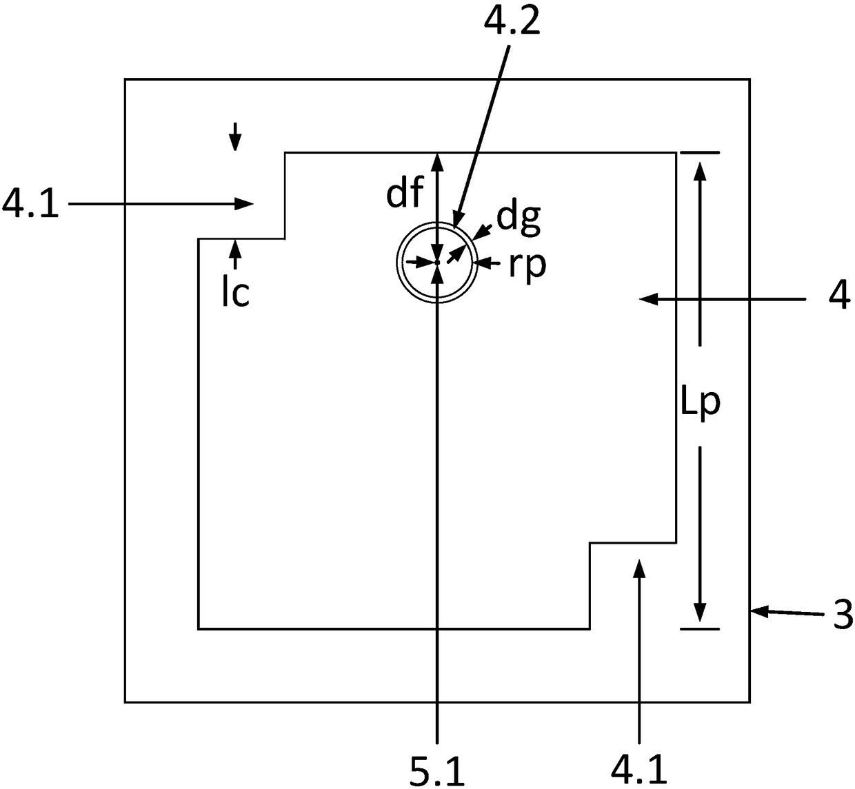
[0027] Such as figure 2 As shown, a circularly polarized UHF RFID reader antenna with easy impedance matching mainly includes ground metal patch 1 parallel to each other, air dielectric layer 2, FR-4 dielectric substrate 3, and radiation patch 4 from bottom to top. It also includes a coaxial feeding probe 5 that feeds vertically to the radiation patch 4 through the ground plane.

[0028] Such as figure 1 , figure 2 As shown, the radiation patch 4 is fed through the coaxial feeding probe 5, and the thickness h of the air dielectric layer 2 is proportional to the ratio bandwidth of the circular polarization axis.

[0029] Such as figure 1 As shown, the radiation patch 4 is a square with a squa...


PUM


Abstract

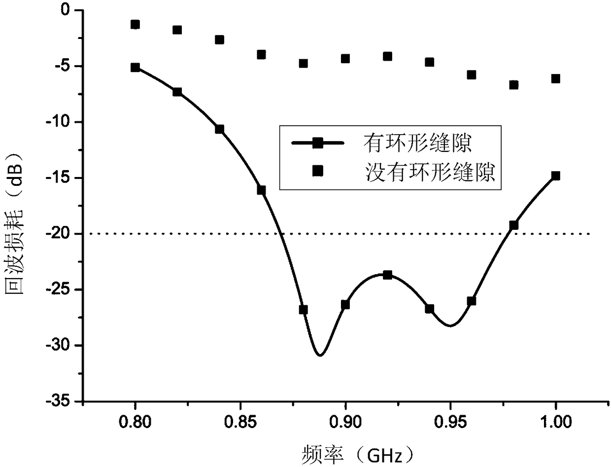
The invention discloses a circularly polarized UHF RFID reader-writer antenna with easy impedance matching, which is characterized by comprising a grounding plate, an air dielectric layer, an FR-4 dielectric substrate, and a radiation patch from bottom to top, which are parallel to one another; the radiation patch is a square whose opposite angles are squarely chamfered; the radiation patch includes an annular gap impedance matching unit; the annular gap impedance matching unit is equidistant from the left and right sides of the radiation patch; the inner circle center of the annular gap impedance matching unit is a coaxial feed probe feed point; and the coaxial feed probe is vertically fed to the radiation patch through the grounding plate. The circularly polarized UHF RFID reader-writerantenna with easy impedance matching proposed by the invention can realize circular polarization coverage in the frequency band of 902 to 928 MHz, and the corresponding -20 dB return loss bandwidth reaches 108 MHz (870-978 MHz). The circularly polarized UHF RFID reader-writer antenna with easy impedance matching in the invention has the advantages of simple structure, easiness for optimization, and circular polarization and impedance matching to achieve mutual independence.

Description

technical field [0001] The invention relates to the technical field of RFID antennas, in particular to a circularly polarized UHF RFID reader-writer antenna with easy impedance matching. Background technique [0002] UHF RFID (Radio Frequency Identification Of Ultrahigh Frequency, UHF RFID) is widely used in supply chain management, container management, aviation and railway parcels due to its advantages of long communication distance, fast communication speed, strong anti-collision ability and low cost. management and other fields. As an important part of the UHF RFID system, the reader antenna realizes easy impedance matching and circular polarization characteristics in key frequency bands, which can simplify the complexity of antenna optimization design and improve the distance and distance of the system to identify linearly polarized and low-gain passive tags. Flexibility, increase the countries and regions covered by the UHF RFID system, and meet the low-cost requireme...

Claims


Application Information

Patent Timeline
IPC IPC(8): H01Q1/38
Inventor 罗志勇赵洪图沈勋任仪马国喜张雪杨美美韩弘祖
Owner CHONGQING UNIV OF POSTS & TELECOMM
Learn More