


Quick Research
Generate reliable direction feasibility study reports for your R&D in just a few steps.

Technical Q&A
Discover and master advanced knowledge NOW. Basics, ideas, possibilities, all at once.

Find Solutions
As an expert in R&D theories, this can generate solutions to your technical problems instantly.

Evaluate Feasibility
Analyze your overall solution with one click, know your potential R&D risks in advance.

Monitor Landscape
Get weekly tech updates, stay abreast of the latest tech innovations and key insights.
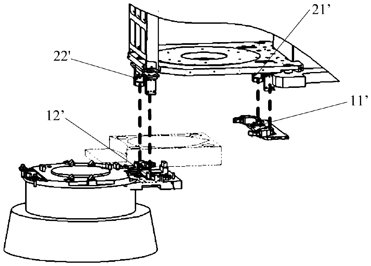
A mask transfer pre-alignment device and method
A pre-alignment and mask technology, applied in the field of mask transmission, can solve the problem of low pre-alignment accuracy and so on
- Summary
- Abstract
- Description
- Claims
- Application Information
AI Technical Summary
Problems solved by technology
Method used
Image

Examples
Embodiment 1
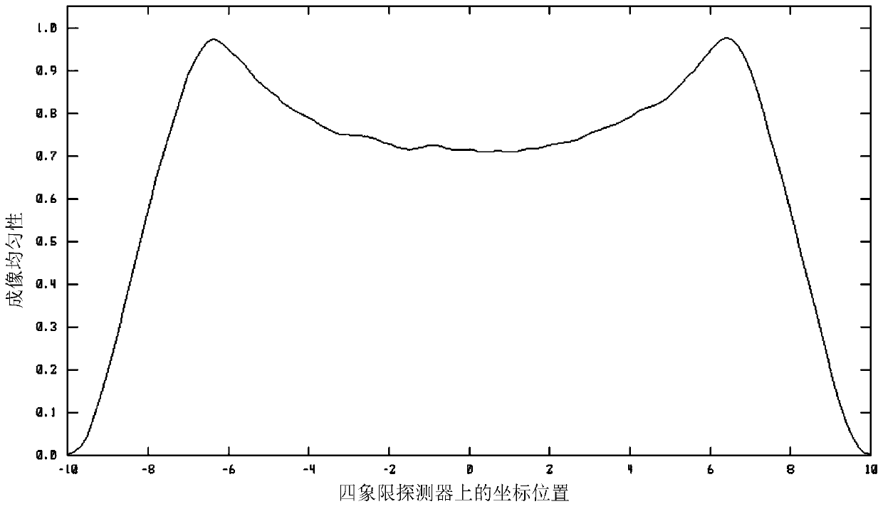
[0057] Such as Figure 4 and Figure 5 As shown, the present invention provides a mask transmission pre-alignment device, which sequentially includes a light source module 100, a pre-alignment test component 200 and an imaging module 300;
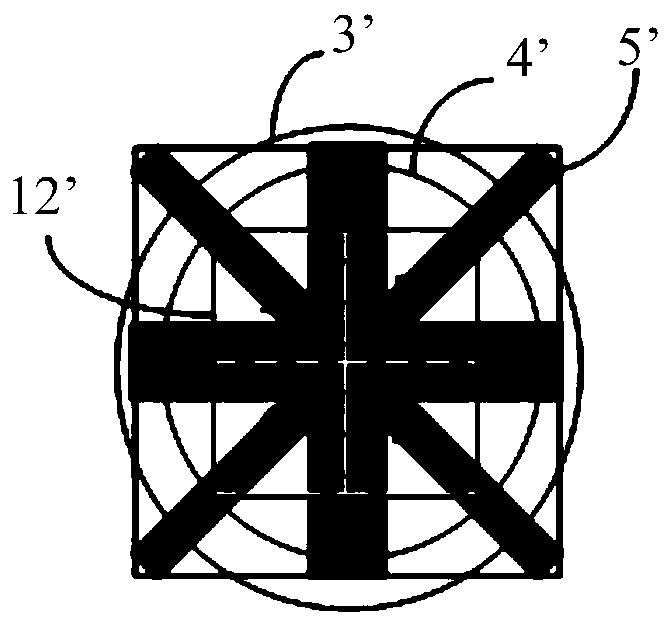
[0058] The light source module 100 sequentially includes a light source 1, a collimation unit 2, and a reticle 3 with a cross mark 31; the light source 1, the collimation unit 2, and the reticle 3 with a cross mark 31 are coaxially arranged, and the positions of the three are opposite to each other. fixed, and installed on the reference plate of the pre-alignment device, the preferred light source 1 is an LED light source that emits LED light, and the collimation unit 2 is an illumination lens that collimates the LED light emitted by the light source 1, with a cross mark The reticle 3 is used to provide components for self-adjusting compensation patterns, and the cross mark 31 therein is opaque. The pre-alignment test part 200 is a reticle ...
Embodiment 2
[0075] Such as Figure 8 As shown, different from Embodiment 1, a second turning prism 8 is also provided between the semi-transparent and semi-reflecting prism 5 and the four-quadrant detector 7 in the present embodiment. At this time, the light source 1, the illumination lens, The reticle 3 with the cross mark 31, the pre-alignment test component 200, the first turning prism 4, the semi-transparent and half-reflecting prism 5, the CCD detector 6, the four-quadrant detector 7 and the second turning prism 8 form a second double far In the imaging system, the light emitted by the light source 1 sequentially passes through the illumination lens, the reticle 3 with the cross mark 31, the pre-alignment test part 200, the first turning prism 4, the semi-transparent and half-reflecting prism 5 and the second turning prism 8, and then enters the The four-quadrant detector 7 performs imaging.
[0076] In summary, the mask transmission pre-alignment device provided by the present inve...
PUM
 Abstract
Description
Claims
Application Information
 - R&D Engineer
- R&D Manager
- IP Professional
- Industry Leading Data Capabilities
- Powerful AI technology
- Patent DNA Extraction
Browse by: Latest US Patents, China's latest patents, Technical Efficacy Thesaurus, Application Domain, Technology Topic, Popular Technical Reports.
© 2024 PatSnap. All rights reserved.Legal|Privacy policy|Modern Slavery Act Transparency Statement|Sitemap|About US| Contact US: help@patsnap.com