
Evaporator steam conveying pipe heat preservation device for biological pharmacy

A technology for biopharmaceuticals and pipelines, which is applied in pipeline protection, heat preservation, and pipeline protection through heat insulation. It can solve problems such as performance degradation, poor hydrophobicity, and poor heat preservation conditions, and achieve the goal of improving heat preservation effects and pressure resistance. Effect

Inactive Publication Date: 2018-09-07
HUBEI ZANBO INFORMATION TECH CO LTD
View PDF0 Cites 1 Cited by
  • Summary
  • Abstract
  • Description
  • Claims
  • Application Information

AI Technical Summary

Problems solved by technology

[0003] If the diameter exceeds the direct buried steam pipeline, if the insulation condition is poor, the temperature drop is large, and the pressure drop is large, it will lead to a huge loss of heat dissipation, resulting in energy waste.
At present, most commonly used insulation materials are simply using rock wool or aluminum silicate for insulation.
Although the cost of rock wool is relatively low, its hydrophobicity is poor, it is difficult to restore the original function after soaking in water, the performance decreases, the volume is large, the fiber length is short, and the thermal insulation performance is poor.
Although aluminum silicate has good mechanical properties and thermal insulation properties, it has a big limitation that the man-made fibers released into the air during installation and construction will cause damage to human tissues, which is not an environmentally friendly product.
Although the cost of the above two thermal insulation structures is relatively low, a single filling medium still cannot achieve a good thermal insulation effect

Method used


Image

  • Evaporator steam conveying pipe heat preservation device for biological pharmacy
  • Evaporator steam conveying pipe heat preservation device for biological pharmacy
  • Evaporator steam conveying pipe heat preservation device for biological pharmacy

Examples


Embodiment Construction

[0021] The following will clearly and completely describe the technical solutions in the embodiments of the present invention with reference to the accompanying drawings in the embodiments of the present invention. Obviously, the described embodiments are only some, not all, embodiments of the present invention.

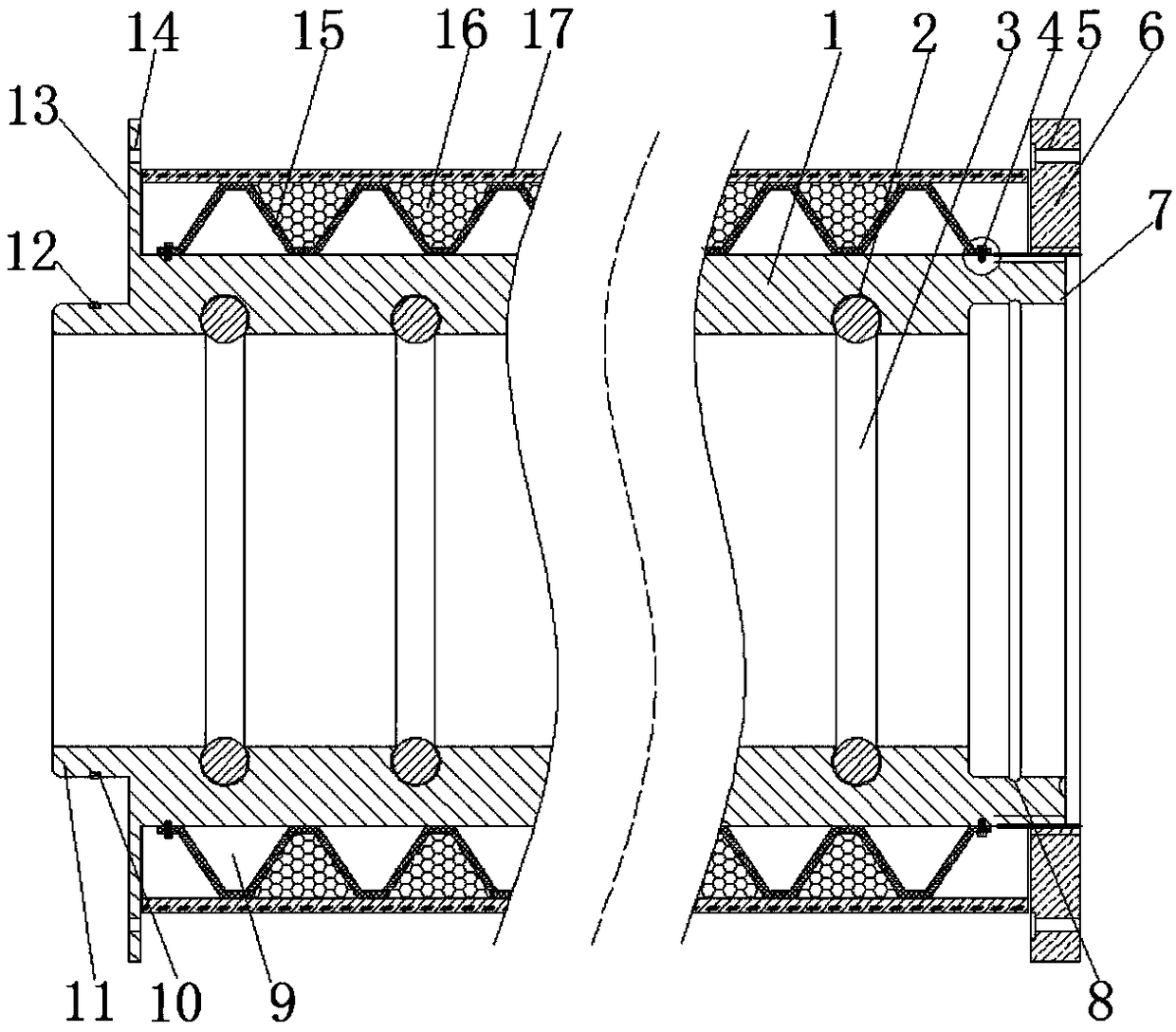
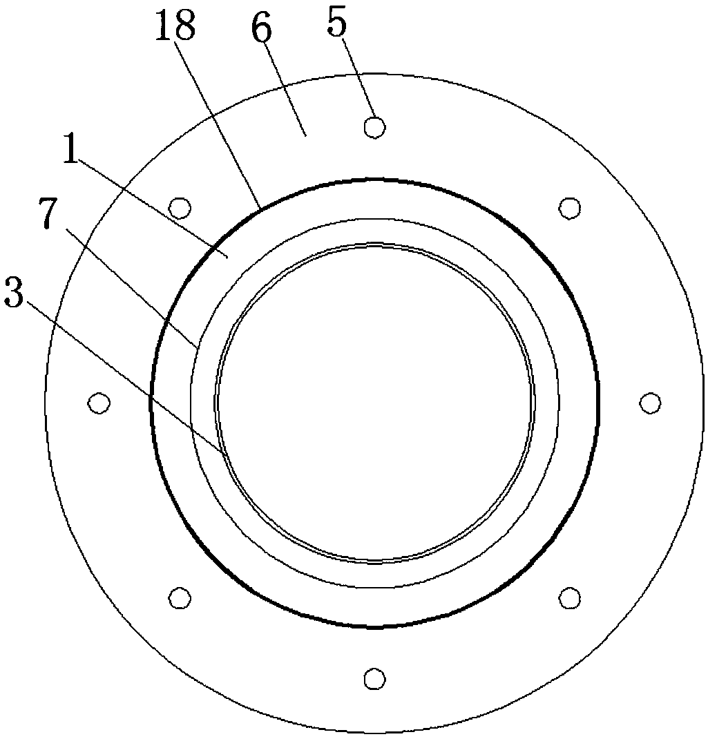
[0022] refer to Figure 1-3 , a thermal insulation device for steam delivery pipelines for evaporators used in biopharmaceuticals, comprising a sleeve body 1 made of rubber material with good ductility, and the transverse depth of the annular shoulder 7 is greater than that of the annular convex tube 11, which is convenient for two sleeves The main body 1 is butted, and the longitudinal depth of the annular shoulder 7 is equal to the wall thickness of the annular convex tube 11, the cross section of the rubber ring 3 is circular, and the cross section of the rubber ring groove is a semicircle including the center of the circle, and the bellows Between the inner wall ...


PUM


Abstract

The invention discloses an evaporator steam conveying pipe heat preservation device for biological pharmacy. The evaporator steam conveying pipe heat preservation device comprises sleeve bodies, rubber ring clamping grooves distributed at equal intervals are formed in the circumferential inner walls of the sleeve bodies, rubber rings are clamped to the interiors of the rubber ring clamping grooves, an annular cutting shoulder is formed in the inner wall of a pipe opening of one end of each sleeve body, a sealing ring clamping groove is formed in the circumferential inner wall of each annular cutting shoulder, the end, far away from the corresponding annular cutting shoulder, of each sleeve body extends close to the inner wall to form an annular protruding pipe, an annular groove is formedin the circumferential outer wall of each annular protruding pipe, a sealing ring is clamped into each annular groove, the circumferential outer wall of each sleeve body is sleeved with a corrugated pipe, the circumferential outer wall of each corrugated pipe is sleeved with an outer pipe, and equal-distance annular first cavities are reserved between the outer walls of the corrugated pipes and the inner walls of the outer pipes. By means of the evaporator steam conveying pipe heat preservation device, the two sleeve bodies can be clamped together more tightly when being in butt joint, and influences of swing of the joints due to joint gaps on the gas tightness of the pipes are avoided.

Description

technical field [0001] The invention relates to the technical field of heat preservation of steam conveying pipes, in particular to a heat preservation device for steam conveying pipes of evaporators used in biopharmaceuticals. Background technique [0002] The structure of the steam insulation pipe is: outer protection layer, insulation layer and anti-leakage layer. The material of the outer protection layer is polyethylene jacket pipe or glass fiber reinforced plastic or other materials. [0003] For direct-buried steam pipes with a diameter larger than that, if the insulation condition is poor, the temperature drop is large, and the pressure drop is large, it will lead to huge heat dissipation loss, resulting in energy waste. At present, most commonly used insulation materials are simply using rock wool or aluminum silicate for insulation. Although the cost of rock wool is relatively low, its hydrophobicity is poor, and it is difficult to restore the original function af...

Claims


Application Information

Patent Timeline
IPC IPC(8): F16L59/02F16L59/12
CPCF16L59/02F16L59/12
Inventor 龚明李世林严小林敖敏
Owner HUBEI ZANBO INFORMATION TECH CO LTD
Learn More