
Caster mixed type hydraulic mechanical leg and control method

A technology of hydraulic machinery and control methods, which is applied in the direction of casters, wheels, fluid pressure actuation devices, etc., can solve the problems of difficulty in robot stable braking control, inability to realize automatic braking, and poor stability of braking conditions, so as to avoid Manual braking method, low processing cost and convenient control

Inactive Publication Date: 2018-09-07
HARBIN UNIV OF SCI & TECH
View PDF9 Cites 3 Cited by
  • Summary
  • Abstract
  • Description
  • Claims
  • Application Information

AI Technical Summary

Problems solved by technology

[0002] With the rapid development of industrial machinery automation, more and more mechanical devices or robots have become highly automated, but most of the mechanical devices can only achieve sliding by installing traditional mechanical pulleys, and cannot achieve automatic braking. The pulley can be braked by manually operating the brake. Such a braking situation is poor in stability and has potential safety hazards. At present, most robots are sliding robots, and it is difficult to control the stable braking of the robot. Multi-legged walking robots do not use pulleys. Although the stability of its standing can be controlled, the current control method is difficult to achieve when it needs to move quickly, which is also the bottleneck that limits the rapid movement of the robot; in order to achieve the rapid mobility of the mechanical device, automatic braking and its standing when braking The stability of the robot can realize the rapidity of the robot's movement, the stability of its standing and the simplicity of the control. The caster hybrid hydraulic mechanical legs can be installed on the relevant mechanical devices or robots, and the mechanical devices or robots can be realized through the expansion and contraction of the hydraulic mechanical legs. Standing steadily and moving quickly

Method used


Image

  • Caster mixed type hydraulic mechanical leg and control method
  • Caster mixed type hydraulic mechanical leg and control method
  • Caster mixed type hydraulic mechanical leg and control method

Examples


Embodiment Construction

[0021] Further illustrate concrete structure and embodiment of the present invention below in conjunction with accompanying drawing:

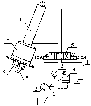
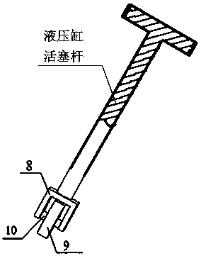
[0022] combine Figures 1 to 6 , the structural composition of the present invention includes: fuel tank (1), pump (2), pressure gauge (3), overflow valve (4), electromagnetic reversing valve (5), hydraulic cylinder (6), standing feet (7) , roller (8), roller shaft (9), roller support width (10); the path of the oil supply tank (1) is connected to the port of the electromagnetic reversing valve (5), and the port of the electromagnetic reversing valve (5) Connect with the two-way oil port of the hydraulic cylinder (6).

[0023] The assembly process of the caster hybrid hydraulic mechanical leg of the present invention is as follows: first pass the piston rod of the hydraulic cylinder (6) through the through hole of the standing foot (7) structure, and then connect the external thread of the standing foot (7) structure with the hydraulic cylinde...


PUM


Abstract

The invention relates to a caster mixed type hydraulic mechanical leg and a control method. The caster mixed type hydraulic mechanical leg comprises a control system, a hydraulic cylinder, a standingleg, a rolling wheel, a supporting wheel axle and rolling wheel supporting spokes. The rolling wheel is connected with the rolling wheel axle in a matched mode. The rolling wheel axle is fixedly connected with the rolling wheel supporting spokes. The rolling wheel supporting spokes are welded to the front end of a piston rod of the hydraulic cylinder. The standing leg is in threaded connection with the inner wall, located at the output end of the piston rod, of the hydraulic cylinder. The caster mixed type hydraulic mechanical leg can slide by controlling stretching of the piston rod of the hydraulic cylinder and guaranteeing that the rolling wheel stretches out of the standing leg structure. The caster mixed type hydraulic mechanical leg can stand by controlling retraction of the piston rod of the hydraulic cylinder and guaranteeing that the rolling wheel is withdrawn into the standing leg structure. The caster mixed type hydraulic mechanical leg is concise in structure. The hydrauliccylinder is controlled conveniently. A caster mixed structure can guarantee fast switching of the sliding and standing states. The caster mixed type hydraulic mechanical leg can be used for wheel type mobile mechanical devices or robots.

Description

technical field [0001] The invention relates to a hydraulic mechanical leg, in particular to a caster hybrid hydraulic mechanical leg and a control method. Background technique [0002] With the rapid development of industrial machinery automation, more and more mechanical devices or robots have become highly automated, but most of the mechanical devices can only achieve sliding by installing traditional mechanical pulleys, and cannot achieve automatic braking. The pulley can be braked by manually operating the brake. Such a braking situation is poor in stability and has potential safety hazards. At present, most robots are sliding robots, and it is difficult to control the stable braking of the robot. Multi-legged walking robots do not use pulleys. Although the stability of its standing can be controlled, the current control method is difficult to achieve when it needs to move quickly, which is also the bottleneck that limits the rapid movement of the robot; in order to ach...

Claims


Application Information

Patent Timeline
IPC IPC(8): F15B15/14F15B15/20B60B33/00
CPCF15B15/14B60B33/00F15B15/20
Inventor 李建英王云周康静孙宵
Owner HARBIN UNIV OF SCI & TECH
Learn More