Temperature verification device system and detection method
A calibration device and the technology of the inspection device, which are applied in the field of temperature calibration, can solve the problem that the accuracy control of the detection system cannot keep up with the requirements, etc., and achieve the effects of improving the calibration efficiency, improving the communication quality, and smoothing the system.
- Summary
- Abstract
- Description
- Claims
- Application Information
AI Technical Summary
Problems solved by technology
Method used
Image
Examples
Embodiment 1
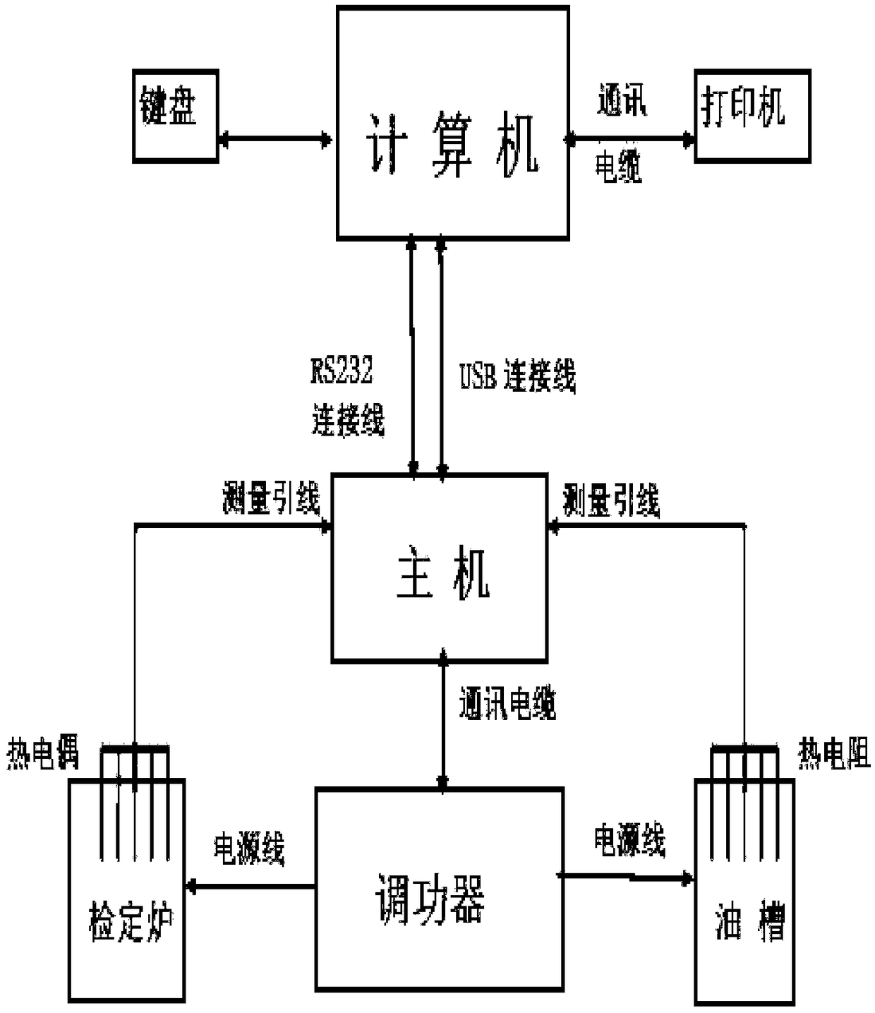
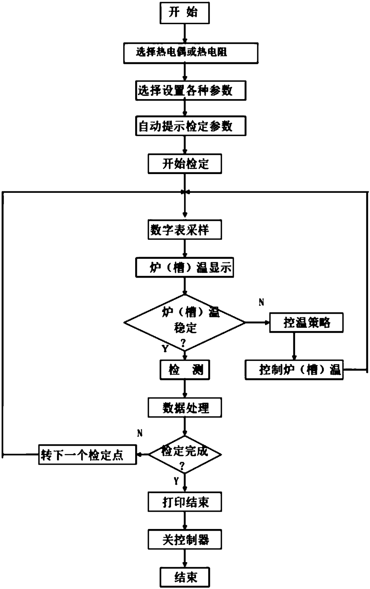
[0053] Such as figure 1 As shown, a temperature verification device system is introduced in this embodiment, including a computer, a verification host, and a power regulator. The verification host includes a first verification host and a second verification host. The power regulator includes a first The power regulator, the second power regulator, and the computer are respectively connected to the first verification host and the second verification host through the communication connection line, the first verification host is connected to the first power regulator, and the second verification host is connected to the second power regulator , the computer sends a control instruction to the verification host, and the verification host controls each power regulator to execute the corresponding operation program after receiving the computer instruction.
[0054] Preferably, when performing verification, the thermocouple to be detected and the standard element are placed in the hon...
Embodiment 2
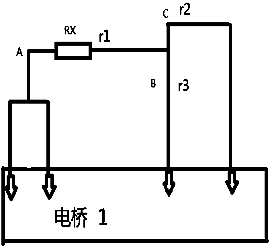
[0059] Such as Figure 3 to Figure 4 As shown, this embodiment introduces a detection method of a temperature inspection device system. The temperature verification device system uses a three-wire connection method when detecting a thermal resistance, and two different connection methods are used to perform two verifications.
[0060] In this embodiment, the thermal resistance is measured twice at the set temperature. In the first measurement, the a terminal of the three-wire thermal resistance is connected to the first input terminal and the second input terminal of the power regulator respectively, and the b terminal and c terminals are respectively connected to the third input terminal and the fourth input terminal of the power regulator, and the obtained resistance value is R1; in the second measurement, the a terminal of the three-wire thermal resistance is respectively connected to the first input terminal of the power regulator. The input terminal is connected to the se...
Embodiment 3
[0067] Such as Figure 5 As shown, a temperature verification device system is introduced in this embodiment. The furnace chamber of the verification furnace has a honeycomb portable temperature element verification device 1, and the honeycomb design element socket of the honeycomb portable temperature element verification device 1 3 places the detection element and the standard part, and connects with the verification furnace through the disc interface 2. The portable temperature element calibration device 1 for the calibration furnace is also designed with a temperature control element inside, a cooling pipe is connected to the tail, and a fan is connected through the fan interface 4 . The temperature control element can control the temperature according to the parameters set by the computer, so that when the verification starts, the temperature in the verification furnace can be quickly controlled to meet the verification requirements. When the verification is completed, th...
PUM
 Abstract
Description
Claims
Application Information
 - R&D
- Intellectual Property
- Life Sciences
- Materials
- Tech Scout
- Unparalleled Data Quality
- Higher Quality Content
- 60% Fewer Hallucinations
Browse by: Latest US Patents, China's latest patents, Technical Efficacy Thesaurus, Application Domain, Technology Topic, Popular Technical Reports.
© 2025 PatSnap. All rights reserved.Legal|Privacy policy|Modern Slavery Act Transparency Statement|Sitemap|About US| Contact US: help@patsnap.com


