
Micro-bubble generating device for biological leaching reactor

A bioleaching and generating device technology, which is applied to specific-purpose bioreactor/fermenter, bioreactor/fermenter combination, biochemical cleaning device, etc., which can solve the problem of limited effect of bubble shear and reduce the service life of the device , accelerate bubble coalescence and other issues

Inactive Publication Date: 2018-09-04
常州扬鹏科技有限公司
View PDF7 Cites 1 Cited by
  • Summary
  • Abstract
  • Description
  • Claims
  • Application Information

AI Technical Summary

Problems solved by technology

However, this way of using the inside of the membrane tube to feed the air and the outside to pass the liquid is only suitable for the gas-liquid two-phase or the case where the solid concentration is very low. If the solid concentration is high, it is easy to accumulate in the shell, causing blockage and reducing the use of the device. life
In addition, the liquid is deflected through the partition outside the membrane tube, which will inevitably cause a lot of energy consumption and accelerate the coalescence of the bubbles, and this method has a limited effect on the shearing of the bubbles.

Method used


Image

  • Micro-bubble generating device for biological leaching reactor
  • Micro-bubble generating device for biological leaching reactor
  • Micro-bubble generating device for biological leaching reactor

Examples


specific example 1

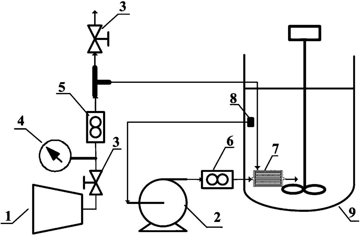
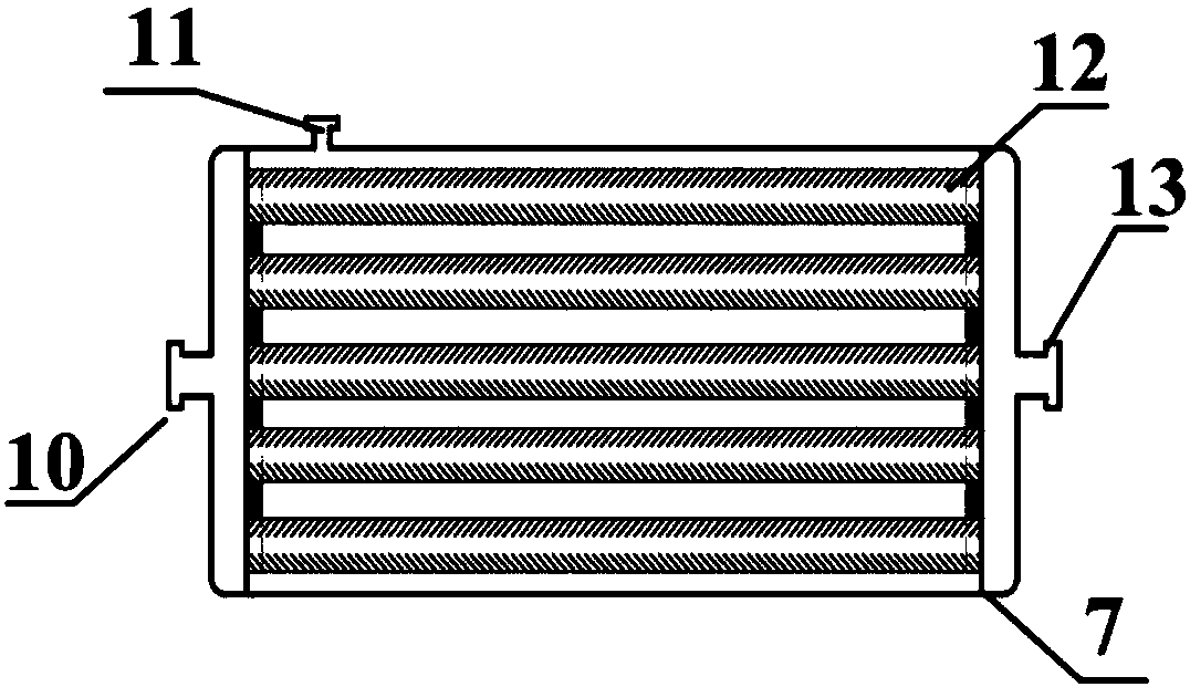
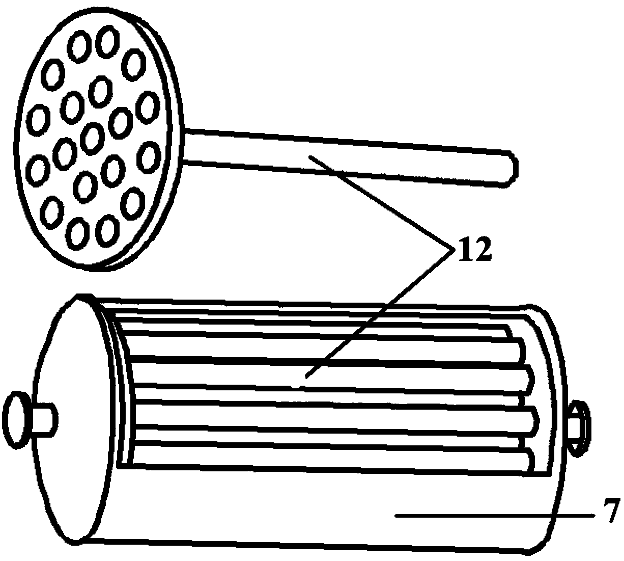
[0049] The membrane module 7 with one membrane tube (1 core), three membrane tubes (3 cores) and seven membrane tubes (7 cores) is used for verification: the membrane tube 12 in the membrane module 7 is an inner membrane single-channel ceramic membrane membrane The shape of the tube, the channel of the membrane tube is circular, the length of the membrane tube is 200 mm, the outer diameter is 30 mm, and the pore diameter is 500 μm. Both are carried out in a bioleaching reactor with an inner diameter of T=190mm and a height of 1.5T. The bottom of the ellipsoid of the bioleaching reactor is T / 4 high, the gas phase is air, the liquid phase is tap water, and the height of the static liquid level is 190mm. The gas flow rate is 20~40L / h.

[0050] The gas pressure generated by the compressor 1 is 0.3MPa, the flow rate is 30L / h, the circulating water flow rate pumped by the circulating pump 2 is 2m / s, and the membrane module 7 adopts 1-core, 3-core and 7-core membrane components.

[...

specific example 2

[0053] The gas pressure generated by compressor 1 is 0.3MPa, the flow rate is 20, 30, 40L / h, the circulating water flow rate pumped by circulating pump 2 is 2m / s, and the membrane module 7 adopts 1-core, 3-core and 7-core membrane components.

[0054] Such as Figure 7 As shown, the mass transfer effect of the multi-core membrane module is better than that of the single-core membrane module under different ventilation rates; The mass transfer coefficient of the module is 26.99% higher than that of the 3-core membrane module.

[0055] In summary, it can be seen that the use of multi-core membrane modules can increase the production capacity and mass transfer effect of microbubbles, and greatly increase the utilization efficiency of air.


PUM

PropertyMeasurementUnit
Outer diameteraaaaaaaaaa
Apertureaaaaaaaaaa

Abstract

The invention discloses a micro-bubble generating device for a biological leaching reactor. The micro-bubble generating device comprises a film assembly capable of being placed in the biological leaching reactor, a gas supplying device used for conveying gas, and a liquid injecting device used for pumping liquid. The film assembly is internally provided with a gas cavity and a film pipe accommodated in the gas cavity. The gas in the gas cavity can enter the film pipe. The gas supplying device and the film assembly are connected so that the gas supplying device can conveniently inject the gas into the gas cavity of the film assembly. The liquid injecting device and the film assembly are connected so that the liquid injecting device can conveniently pump the liquid into the film pipe in thefilm assembly, and the liquid and the gas in the film pipe are mixed to form micro-bubbles to be output into the biological leaching reactor. According to the micro-bubble generating device, lots of the micro-bubbles can be generated, oxygen transferring of the micro-bubbles is greatly improved, and cutting can be conducted by relying on circulating liquid, so that the size of the bubbles is reduced.

Description

technical field [0001] The invention relates to a microbubble generating device for a bioleaching reactor. Background technique [0002] At present, the biochemical reaction in the bioleaching reactor is a complex exothermic reaction involving three phases of gas, liquid and solid. It is required that the reactor is not only suitable for rapid reaction, but also suitable for large-scale reproduction of bacteria. Among them, the dissolved oxygen level and the uniformity of solid phase suspension are two important parameters for evaluating the reactor. [0003] The commonly used bioleaching reactors in industry are stirred tank reactors and airlift reactors (bar tanks). Stirred tank reactors have a high degree of gas-liquid-solid mixing, but they cannot be ventilated at a high speed. The shear generated by rapid stirring is harmful to bacteria. The damage is great. The airlift reactor has the advantages of gas phase dispersion, high heat transfer rate, and rapid mixing. How...

Claims


Application Information

Patent Timeline
IPC IPC(8): C12M1/34C12M1/04C12M1/00B01F3/04
CPCC12M29/16C12M41/34B01F23/2131
Inventor 张伟鹏杨超陈永生陈彦廷李明海
Owner 常州扬鹏科技有限公司
Learn More