High-efficiency rectifier

A rectifier, high-efficiency technology, applied in the direction of high-efficiency power electronic conversion, AC power input conversion to DC power output, output power conversion device, etc., can solve the problems of low circuit efficiency, high switching loss, low power density, etc., to achieve Reduce the influence of parasitic lead reactance, reduce the volume of DC capacitor, and reduce the effect of voltage stress

Inactive Publication Date: 2018-08-28
ZHEJIANG UNIV
View PDF8 Cites 5 Cited by
  • Summary
  • Abstract
  • Description
  • Claims
  • Application Information

AI Technical Summary

Problems solved by technology

However, the conduction loss of the rectifier diode is high, and the diode reverse recovery loss of the boost circuit in the high-frequency switching mode is high, making this type of circuit inefficient and usually only used in low-power applications.
[0004] The bridgeless boost rectifier structure is suitable for single-phase systems. When used in three-phase systems, the three-phase DC outputs of the bridgeless boost rectifier need to be isolated from each other, so the DC capacitor is large in size and low in power density.
[0005] In the document Single inductor three-level bridgeless boost power factorcorrection rectifier with nature voltage clamp (IET Power Electron, 2012.5(3): p.358-365), the Vienna three-level rectifier is mentioned. This type of rectifier passes two switching tubes The control realizes the three-level AC-DC rectification, the conversion efficiency is high, and it is often used in high-power, medium-voltage occasions; however, in this scheme, the diodes are turned on and off at high frequencies, and the reverse recovery loss of the diodes is large
[0006] The use of silicon carbide-based devices can greatly reduce the loss of semiconductor devices in power conversion. The three-level rectifier based on silicon carbide diodes and silicon-based metal-oxide-semiconductor field-effect transistors has a large parasitic capacitance due to the large parasitic capacitance of silicon-based metal-oxide-semiconductor field-effect transistors. Switching losses are still high; however, 3-level rectifiers using SiC diodes and SiC MOSFETs can significantly reduce switching losses, but at a high cost

Method used


Image

  • High-efficiency rectifier
  • High-efficiency rectifier
  • High-efficiency rectifier

Examples


Embodiment Construction

[0020] In order to describe the present invention more specifically, the technical solutions of the present invention will be described in detail below in conjunction with the accompanying drawings and specific embodiments.

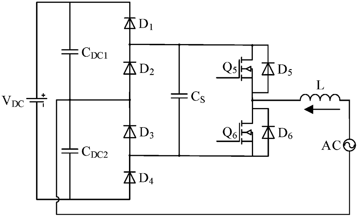
[0021] like figure 1 As shown, the high-efficiency rectifier structure of the present invention includes a DC power supply V DC , voltage dividing capacitor module, two silicon-based diode modules, absorbing capacitor C S , silicon carbide-based metal oxide semiconductor field effect transistor module and filter inductor L; wherein, the voltage dividing capacitor module includes a first DC voltage dividing capacitor C DC1 and the second DC divider capacitor C DC2 The silicon-based diode module includes a first group of silicon-based diode modules and a second group of silicon-based diode modules; the first group of silicon-based diode modules includes a first power diode D 1 and the second power diode D 2 , the second group of silicon-based diode modu...


PUM


Abstract

The invention discloses a high-efficiency rectifier comprising a direct-current power supply, a voltage-dividing capacitor module, two silicon-based diode modules, an absorbing capacitor, a silicon-carbide-based metal-oxide-semiconductor field-effect transistor and a filter inductor. The rectifier is characterized in that only the silicon-carbide-based metal-oxide-semiconductor field-effect transistor has the high-frequency switching action, so that the switching loss is low; and compared with the full-silicon-carbide-based rectifier plan, the high-efficiency rectifier employs the silicon-based power diode, so that the overall cost is lowered. The rectifier is suitable for intermediate-voltage and high-voltage high-power active front-end application occasions.

Description

technical field [0001] The invention belongs to the technical field of power electronics, and in particular relates to a high-efficiency rectifier. Background technique [0002] AC-DC active rectifier technology is a very important part of modern industry. It provides DC power for grid-connected power equipment such as adjustable speed motors, electric vehicle charging piles and communication systems. Its wide application can reduce current harmonics And the additional line loss caused by low power factor, improve energy efficiency, and achieve energy saving and emission reduction. [0003] The simplest active rectification device is a diode rectification input followed by a Boost circuit. This scheme has a simple structure and mature technology. However, the high conduction loss of the rectifier diode and the high reverse recovery loss of the diode in the high-frequency switching mode make this type of circuit inefficient, and it is usually only used in low-power applicati...

Claims


Application Information

Patent Timeline
IPC IPC(8): H02M7/217H02M1/34
CPCH02M1/34H02M7/2173H02M1/0058H02M1/346Y02B70/10
Inventor 李楚杉李武华雷锦涛许德伟
Owner ZHEJIANG UNIV
Why Eureka
Try Eureka