
MEG device and method based on atomic magnetometer/magnetic gradiometer

A technology of atomic magnetism and magnetic gradiometer, which is applied in the field of magnetic brain imaging, can solve the problems of detector spatial position error, high cost, and lack of multi-channel parallel acquisition prototype, etc., to eliminate signal fluctuations, reduce errors, and take into account the flexibility of size sexual effect

Active Publication Date: 2018-08-28
COGNITIVE MEDICAL IMAGING LTD
View PDF14 Cites 23 Cited by
  • Summary
  • Abstract
  • Description
  • Claims
  • Application Information

AI Technical Summary

Problems solved by technology

[0005] First of all, the rigid bracket used to carry the optical atomic magnetometer / magnetic gradiometer needs to be close to the shape of the human head to accurately position the atomic magnetometer / magnetic gradiometer. Each person's specific size and shape of the head needs to be adapted to rigid brackets of different sizes and shapes, which is costly; while a flexible bracket similar to an EEG cap structure will cause errors in the spatial position of the detector due to head movement
[0006] Secondly, at present, there is no real multi-channel parallel acquisition prototype, and there is no magnetometer, magnetic gradiometer detector scheme based on technology and technology that has matured and can be mass-produced. or detection method

Method used


Image

  • MEG device and method based on atomic magnetometer/magnetic gradiometer
  • MEG device and method based on atomic magnetometer/magnetic gradiometer
  • MEG device and method based on atomic magnetometer/magnetic gradiometer

Examples


Embodiment Construction

[0042] In order to make the object, technical solution and advantages of the present invention clearer, the present invention will be further described in detail below in conjunction with specific embodiments and with reference to the accompanying drawings.

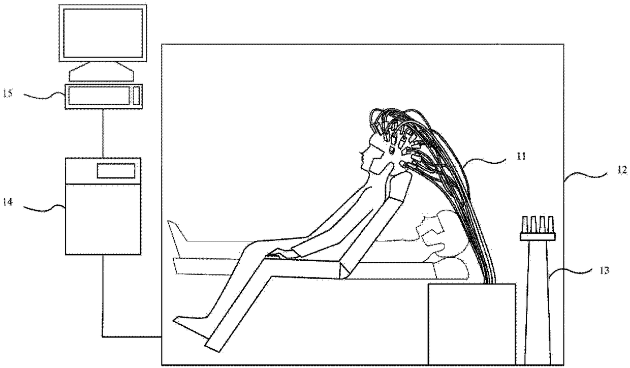
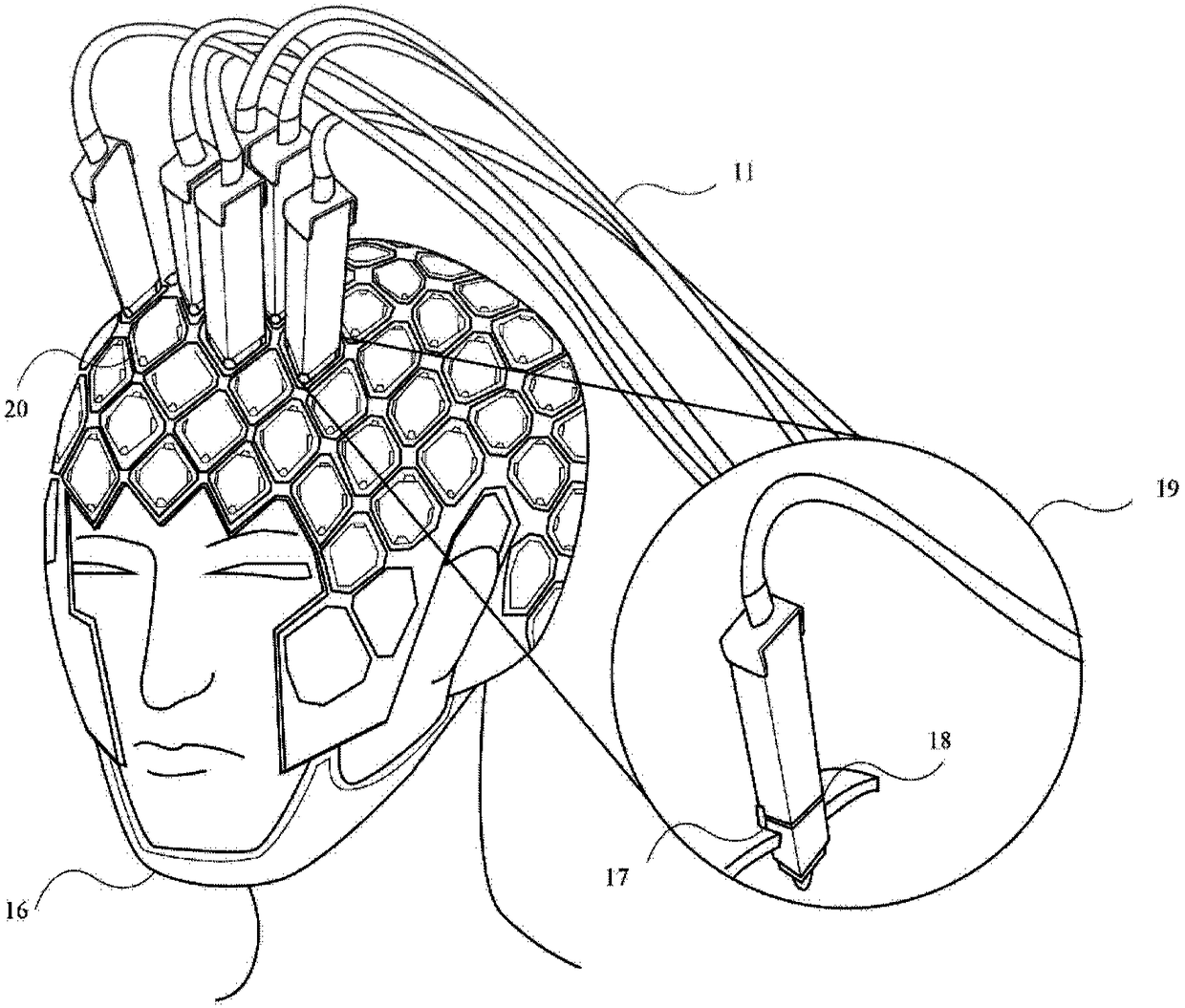
[0043] The invention provides a magnetoencephalogram detection device and method based on an atomic magnetometer / magnetic gradiometer, and proposes a new detector fixing form, which can realize batch and modular production.

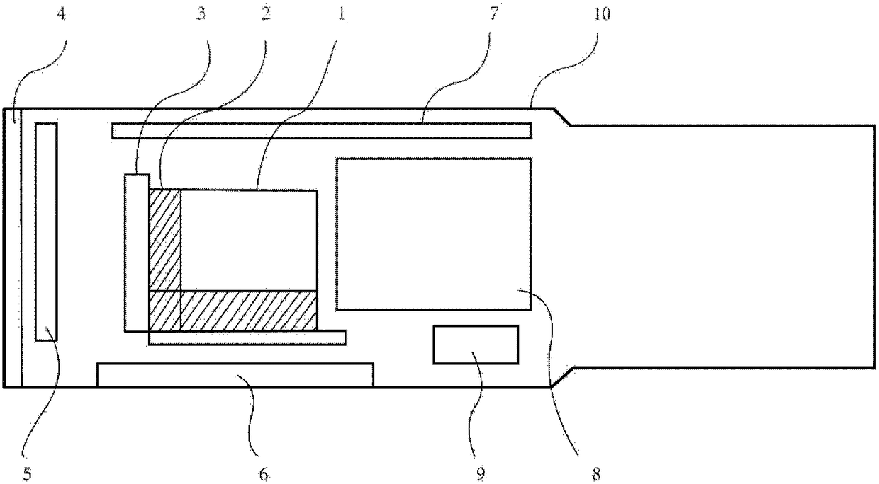
[0044] According to some embodiments, the present invention provides an atomic magnetometer / magnetic gradiometer, which eliminates signal fluctuations caused by beam jitter in traditional optical fiber transmission through a compact fixed optical path; further based on several aforementioned atomic magnetometers A magnetic gradiometer provides a wearable multi-channel parallel acquisition magnetic brain detection device and detection method.

[0045] Such as figure 1 As shown, a kind of atomic magneto...


PUM


Abstract

An atomic magnetometer / magnetic gradiometer comprises at least one detection gas chamber, wherein the detection gas chamber is filled with alkali metal vapor; a laser light source, which is used for emitting an excitation light beam and a detection light beam to irradiate the detection gas chamber, wherein the excitation light beam is used for enabling alkali metal vapor in the detection gas chamber to be polarized, and the detection light beam is used as polarized light to pass through the alkali metal vapor and then reach the polarization detection device; a modulation coil which is used forgenerating a modulation magnetic field with the known intensity for the alkali metal vapor; a polarization detection device which is used for receiving the detection light beam, and according to thepolarization angle change information of the to-be-measured magnetic field overlapped by the modulated magnetic field, the polarization angle change information of the light beam is detected, and of the detection light beam in a to-be-measured magnetic field subjected to superposition by the modulation magnetic field, acquiring detection signals of magnetic field intensity or magnetic field gradient of the to-be-measured magnetic field. The invention further provides a MEG device and method based on the atomic magnetometer / the magnetic gradiometer. The invention is based on a discrete atomicmagnetometer / the magnetic gradiometer, and realizes the detecting of the brain magnetic signals of the wearable multi-channel detection of MEG signals.

Description

technical field [0001] The invention relates to the technical field of magnetoencephalography, in particular to a magnetoencephalogram detection device and method based on an atomic magnetometer / magnetic gradiometer. Background technique [0002] Magnetoencephalography (MEG) is a method used to detect extremely weak magnetic signals produced by neural electrical activity in the brain. The time resolution of magnetoencephalography is very high, which can reach less than 1ms, and the magnetic signal related to high-frequency electrical activity will not be attenuated in the process of transmitting out of the brain. ) and extremely high spatial accuracy (the magnetic permeability of different human tissues is basically the same, and will not cause distortion to the magnetic field). Due to its high spatio-temporal resolution, magnetoencephalography is not only an effective technical means to study the mechanism of neural activity in the brain and clinical diagnosis of epilepsy ...

Claims


Application Information

Patent Timeline
IPC IPC(8): G01R33/022G01R33/032
CPCG01R33/022G01R33/032
Inventor 王帆卓彦
Owner COGNITIVE MEDICAL IMAGING LTD
Learn More