Reforming system

A reforming system and reforming gas technology, applied in the direction of charging system, combustion air/combustion-air treatment, machine/engine, etc., can solve the problems of reforming efficiency drop, mixed gas temperature drop, and difficulty in obtaining activation temperature , to achieve the effect of improving the reforming efficiency and increasing the generation of hydrogen

Pending Publication Date: 2018-08-28
HYUNDAI MOTOR CO LTD +1
View PDF6 Cites 5 Cited by
  • Summary
  • Abstract
  • Description
  • Claims
  • Application Information

AI Technical Summary

Problems solved by technology

In addition, the EGR gas must be sufficiently heated to obtain a sufficient fuel reforming activation temperature, however, it is difficult to obtain the activation temperature depending on the driving conditions and the supply amount of EGR gas
We have found that there is a problem of a drop in reforming efficiency due to a significant drop in the temperature of the mixed gas during the mixing of fuel and EGR gas in the mixing section of the fuel reformer

Method used


Image

  • Reforming system
  • Reforming system
  • Reforming system

Examples


Embodiment Construction

[0037] The following description is merely exemplary in nature and is not intended to limit the disclosure, application or uses. It should be understood that throughout the drawings, corresponding reference numerals indicate like or corresponding parts and features.

[0038] As those skilled in the art would realize, the forms described may be modified in various different ways, all without departing from the spirit or scope of the present disclosure.

[0039] Further, in the exemplary forms, since the same reference numerals denote the same elements having the same configuration, the first exemplary form is representatively described, and in other exemplary forms, only the same elements as the first exemplary form will be described. Exemplary form different configurations.

[0040] The figures are schematic and not to scale. Relative sizes and proportions of parts shown in the drawings are exaggerated or reduced in size for clarity and convenience, and the sizes are merely ...


PUM


Abstract

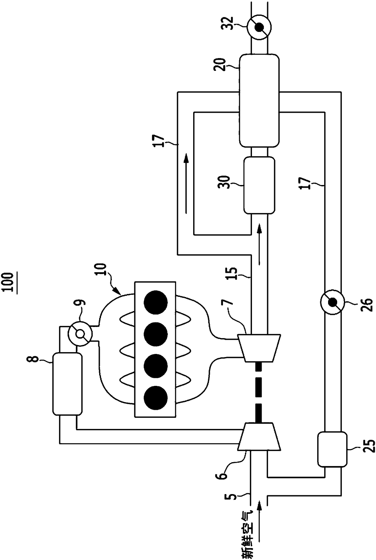
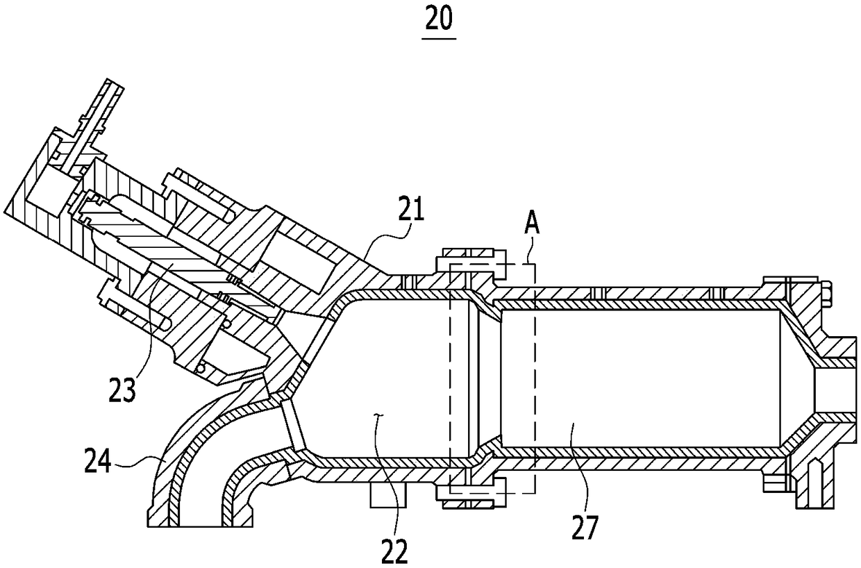
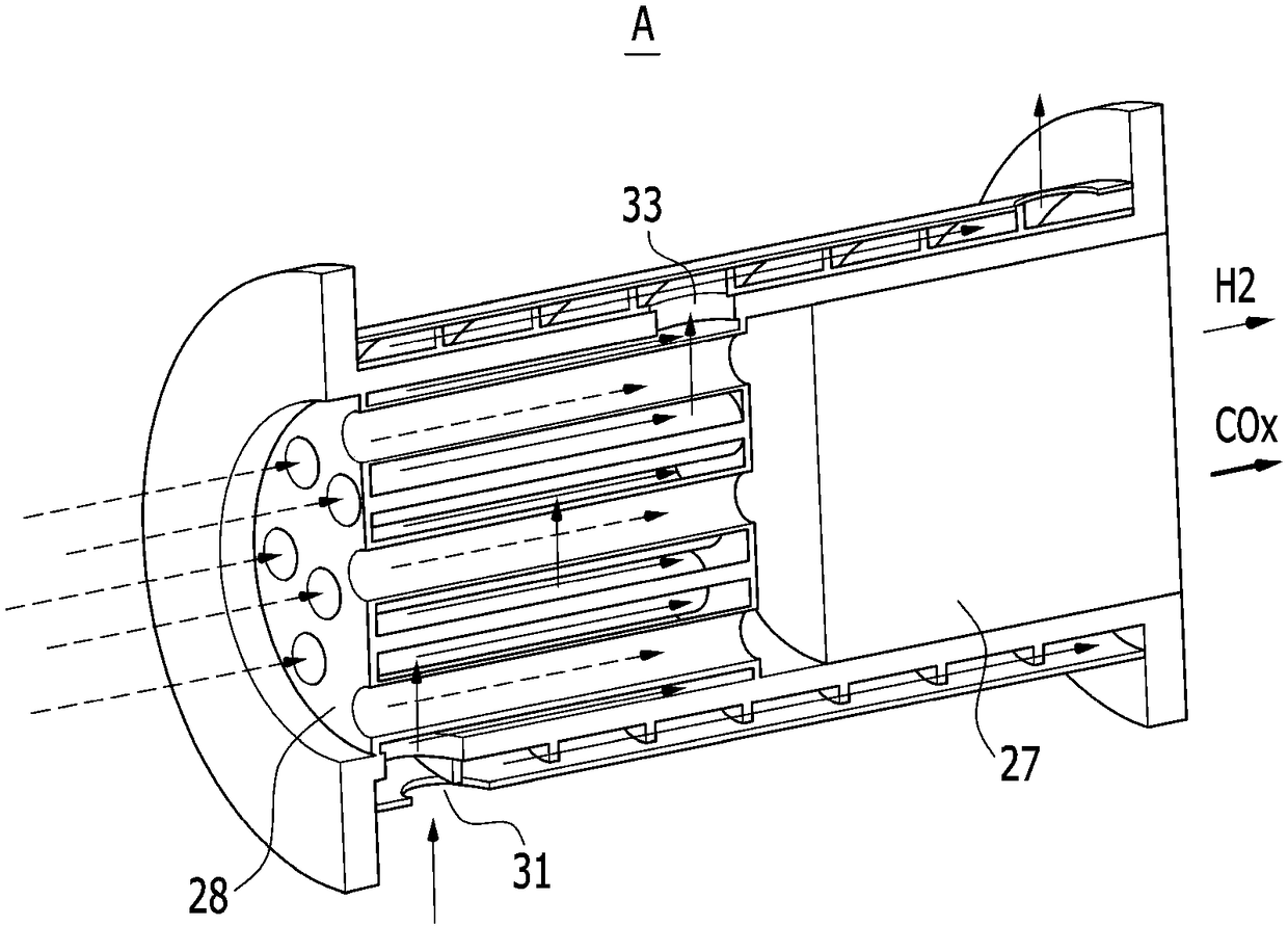
The invention discloses a fuel reforming system. The fuel reforming system includes: an engine combusting reformed gas to generate mechanical power; an intake line connected to the engine to supply the reformed gas and air to the engine; an exhaust line connected to the engine to circulate the exhaust gas discharged from the engine; a fuel reformer provided at an exhaust gas recirculation (EGR) line diverging from the exhaust line; and a catalyst disposed at the exhaust line and purifying nitrogen oxide included in the exhaust gas at a front end of the fuel reformer. In particular, the fuel reformer mixes the fuel with the EGR gas which is a part of the exhaust gas and passes through the EGR line, and reforms the fuel mixed in the EGR gas.

Description

[0001] Cross References to Related Applications [0002] This application claims priority and benefit from Korean Patent Application No. 10-2016-0169865 filed on December 13, 2016, the entire contents of which are incorporated herein by reference. technical field [0003] The present disclosure relates to a fuel reforming system. Background technique [0004] The statements in this section merely provide background information related to the present disclosure and may not constitute prior art. [0005] Generally, an exhaust gas recirculation (EGR) system is a system installed in a vehicle to reduce harmful exhaust gas. [0006] The exhaust gas recirculation system reduces the oxygen content in the mixer, reduces the amount of exhaust gas, and reduces toxic substances in the exhaust gas by circulating a part of the exhaust gas exhausted from the engine. [0007] Also, the temperature of the exhaust gas discharged from the engine is high, so the engine efficiency can be impr...

Claims


Application Information

Patent Timeline
Patent Type & Authority Applications(China)
IPC IPC(8): F02M26/36F01N3/20
CPCF01N3/20F01N2570/14F02M26/36F01N3/0814F01N3/0842F01N2240/30F01N2240/36F01N2410/00F02M26/06F02M26/15F02M26/30F01N3/08F01N3/2066F02M27/02F02M35/10216F02M26/17F02M26/22F02M26/52F02M37/30F01N3/0234F01N3/0235F02M26/00
Inventor 李昇祐白洪吉李太源
Owner HYUNDAI MOTOR CO LTD
Why Eureka
Try Eureka