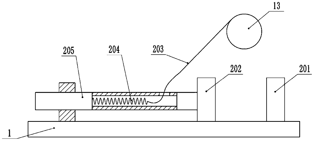
Pipe cutting and grinding device
A technology for cutting and grinding pipes, used in positioning devices, grinding machines, grinding workpiece supports, etc., can solve the problems of large workload, labor and material resources, and time consumption, and achieve simplified operation steps, good grinding effect, and improved efficiency. The effect of work efficiency
Active Publication Date: 2020-04-21
苏州市振渭城镇建设发展有限公司
View PDF12 Cites 1 Cited by
- Summary
- Abstract
- Description
- Claims
- Application Information
AI Technical Summary
Problems solved by technology
[0002] Pipe fittings are widely used in today's society. Pipe fittings are parts that connect pipes into pipelines. During the production process of pipe fittings, steel pipes need to be cut, and steel pipes are cut into small sections according to various specifications and sizes. The net weight is relatively large, and the length is also long. The general method is to fix the steel pipe first, and then use a cutting machine to cut the required length. Manual feeding consumes manpower and material resources. The cut steel pipe is cut at both ends after cutting the head and tail. There will be internal and external burrs. Workers generally use a flat file to remove the external burrs, and remove the internal burrs with a conical knife. However, the hardness of the internal burrs after cutting is also greatly improved due to the high temperature generated during the cutting process. Therefore, the cut surface of the steel pipe The grinding work needs to consume a lot of time, resulting in a heavy workload for workers, so it is necessary to propose a steel pipe cutting device that automatically grinds the cut
Method used
View moreImage
Smart ImageViewing Examples
Examples
Embodiment Construction
[0015] The present invention will be described in further detail below by means of specific embodiments:
Login to View More PUM
 Abstract
The invention belongs to the technical field of cutting equipment, and specifically discloses a pipe cutting and grinding device. The pipe cutting and grinding device comprises a cutting mechanism anda grinding mechanism which are connected to the same rotating shaft, wherein a transmission gear and two fixed pulleys are arranged on the rotating shaft; a rack which is fixed to a machine frame isengaged with the transmission gear; the grinding mechanism comprises a rotating barrel which is fixed to the rotating shaft, and a grinding plate is arranged on the rotating barrel; a square shaft isin sliding connection with the interior of the rotating barrel, and a threaded rod which is in thread connection with the rotating barrel is rotatably connected to the square shaft; and the threaded rod is in sliding connection with a sliding plate, and the sliding plate is in sliding connection with the machine frame. The pipe cutting and grinding device further comprises a conveying roller, a first clamping mechanism and a second clamping mechanism; the first clamping mechanism comprises a clamping block and a fixing block; a sliding rope is connected between the clamping block and the corresponding fixed pulley; the second clamping mechanism is in sliding connection with a working platform; a baffle plate is arranged at the left end of the working platform; and magnetic parts which areattracted to and repelled by each other are arranged between the baffle plate and the second clamping mechanism. According to the scheme, the pipe cutting and grinding device has the advantages that anotch of a steel pipe can be ground while the steel pipe is cut, so that the working efficiency is improved.
Description
technical field [0001] The invention belongs to the technical field of cutting equipment, in particular to a pipe cutting and grinding device. Background technique [0002] Pipe fittings are widely used in today's society. Pipe fittings are parts that connect pipes into pipelines. During the production process of pipe fittings, steel pipes need to be cut, and steel pipes are cut into small sections according to various specifications and sizes. The net weight is relatively large, and the length is also long. The general method is to fix the steel pipe first, and then use a cutting machine to cut the required length. Manual feeding consumes manpower and material resources. The cut steel pipe is cut at both ends after cutting the head and tail. There will be internal and external burrs. Workers generally use a flat file to remove the external burrs, and remove the internal burrs with a conical knife. However, the hardness of the internal burrs after cutting is also greatly imp...
Claims
Login to View More Application Information
Patent Timeline
 Patent Type & Authority Patents(China)
IPC IPC(8): B23P23/04B23Q3/06B23Q7/05B24B9/04B24B41/06
CPCB23P23/04B23Q3/064B23Q7/05B24B9/04B24B41/067
Inventor 李志华
Owner 苏州市振渭城镇建设发展有限公司
Features
- R&D
- Intellectual Property
- Life Sciences
- Materials
- Tech Scout
- Unparalleled Data Quality
- Higher Quality Content
- 60% Fewer Hallucinations
Learn More Browse by: Latest US Patents, China's latest patents, Technical Efficacy Thesaurus, Application Domain, Technology Topic, Popular Technical Reports.
© 2025 PatSnap. All rights reserved.Legal|Privacy policy|Modern Slavery Act Transparency Statement|Sitemap|About US| Contact US: help@patsnap.com


