


Quick Research
Generate reliable direction feasibility study reports for your R&D in just a few steps.

Technical Q&A
Discover and master advanced knowledge NOW. Basics, ideas, possibilities, all at once.

Find Solutions
As an expert in R&D theories, this can generate solutions to your technical problems instantly.

Evaluate Feasibility
Analyze your overall solution with one click, know your potential R&D risks in advance.

Monitor Landscape
Get weekly tech updates, stay abreast of the latest tech innovations and key insights.
Grain drying equipment with rapid cooling function
A grain drying and rapid cooling technology, which is applied to grain drying, drying solid materials, lighting and heating equipment, etc., can solve the problems such as moisture return of grain particles, save time and cost, improve the uniformity of heating, and avoid scorching.
- Summary
- Abstract
- Description
- Claims
- Application Information
AI Technical Summary
Problems solved by technology
Method used
Image

Examples
Embodiment 1
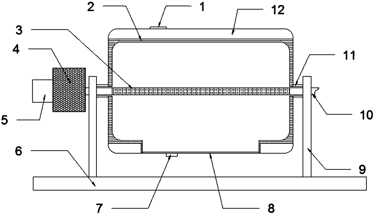
[0027] Grain drying equipment with rapid cooling, including a base 6, a bracket 9 installed on the base, a drying cylinder 1 that rotates with the bracket 9 through a shaft 11, and a ventilation pipe 10 with a hollow structure installed in the inner cavity of the drying cylinder The top of the drying cylinder 2 is provided with a feed hole 1, the bottom is provided with a discharge port 8, a heating layer is integrated in the cylinder wall, and a cooling water jacket is provided outside the cylinder wall; the shaft rod 7 has a shaft hole; Both ends of the ventilation pipe 2 protrude from the shaft hole and pass through the bracket; the ventilation pipe 3 is provided with a ventilation hole 3 on the pipe wall inside the drying cylinder 3 .
Embodiment 2
[0029] Based on Embodiment 1, in order to improve the moisture absorption efficiency of the air flowing through the ventilation pipe, the following improvements are made: one end of the ventilation pipe 10 is provided with a drying device; The tuyere 5; the inside of the drying box 4 is filled with a desiccant.
[0030] Through the function of the drying device, the humidity of the air flowing through the inside of the ventilation pipe is reduced, and the humidity difference between the inside of the ventilation pipe and the inside of the drying cylinder is enlarged. Driven by the physical effect of humidity difference, the moisture in the drying cylinder is more likely to escape into the ventilation pipe through the ventilation holes and be taken out, which further reduces the humidity in the drying cylinder and reduces the degree of moisture regain of grain particles in the subsequent cooling step.
Embodiment 3
[0032] Based on Embodiment 1, in order to weaken the influence of the resistance of the drying box on the speed of air flowing into the ventilation pipe, the following improvements are made: the diameter of the air inlet 5 is larger than the diameter of the ventilation pipe 10 .
[0033] Through the design of the size of the air inlet, the drying box is equipped with the function of a booster device. While offsetting its resistance, it can maintain or increase the flow rate of the air after passing through the drying box, thus ensuring the negative pressure effect generated when flowing through the ventilation pipe.
PUM
 Abstract
Description
Claims
Application Information
 - R&D Engineer
- R&D Manager
- IP Professional
- Industry Leading Data Capabilities
- Powerful AI technology
- Patent DNA Extraction
Browse by: Latest US Patents, China's latest patents, Technical Efficacy Thesaurus, Application Domain, Technology Topic, Popular Technical Reports.
© 2024 PatSnap. All rights reserved.Legal|Privacy policy|Modern Slavery Act Transparency Statement|Sitemap|About US| Contact US: help@patsnap.com