Heat storage device for dryer

A technology of heat storage device and dryer, applied in drying chamber/container, dry gas arrangement, solar heat storage, etc., can solve the problems of shortened continuous drying time, poor drying effect, short heat storage time, etc., and achieve solar energy utilization rate Improve and improve the effect of heat preservation and high utilization rate of heat energy

Inactive Publication Date: 2018-08-24
GUIZHOU UNIV
View PDF7 Cites 0 Cited by
  • Summary
  • Abstract
  • Description
  • Claims
  • Application Information

AI Technical Summary

Problems solved by technology

[0003] At present, there are mainly two types of solar dryers: one is a common greenhouse-type solar drying device, and the other is a collector-type solar drying device. The air collector and drying chamber of this drying device are separated. , can be better combined with the conventional energy air heating system to form a large-scale hybrid solar drying device with continuous operation, but the drying heat transfer process is mainly convective heat transfer, and there is an additional heat exchange process between solar energy and materials , the drying efficiency is lower than that of ordinary greenhouse-type solar drying devices
However, the existing heat storage time is short. After the sun sets, the continuous drying time is greatly shortened, the temperature drops suddenly, the drying effect is poor, and the efficiency is also reduced.

Method used


Image

  • Heat storage device for dryer
  • Heat storage device for dryer
  • Heat storage device for dryer

Examples


Embodiment 1

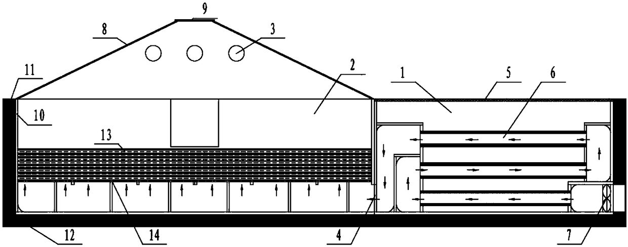
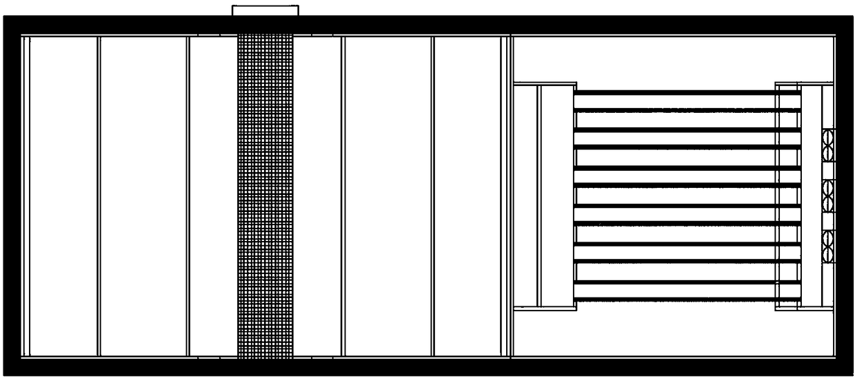
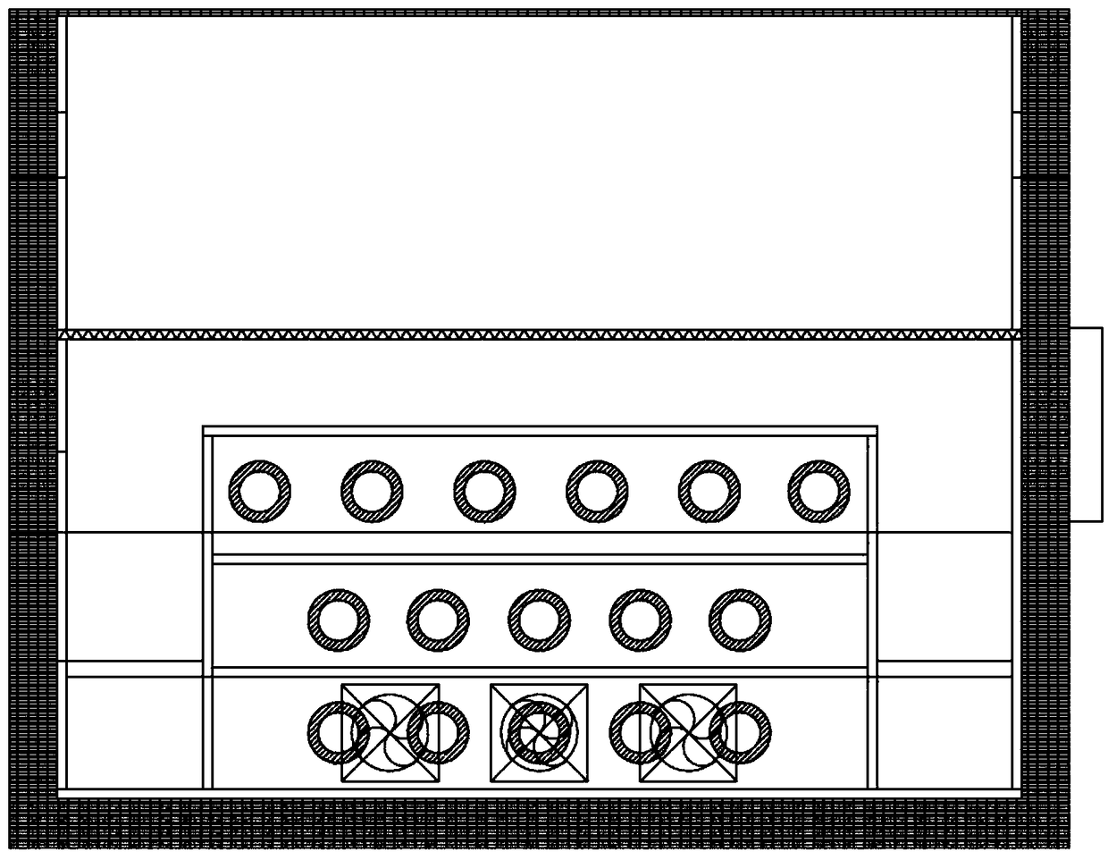
[0032] Example 1: Such as Figure 1-Figure 6 As shown, a heat storage device for a dryer includes an air inlet 4 connected to the heat storage chamber 1 at the bottom of the left side of the heat storage chamber 1, a linear Fresnel lens 5 at the top, and heat storage copper installed inside The tube 6, the heat storage copper tube 6 is connected with a fan 7, and the heat storage copper tube is made of high thermal conductivity copper. The outer wall of the heat storage chamber 1 and the drying chamber 2 is an integral structure, separated by partitions.

[0033] Preferably, the side wall of the heat storage chamber 1 includes an insulation layer 11 and an aluminum alloy layer 12 from the inside to the outside. The insulation layer is made of aluminum silicate, and the aluminum alloy tube layer plays a protective role.

[0034] Preferably, the above-mentioned material placement layer 13 adopts a drawer structure with multiple layers, and is supported by a frame-shaped bracket 14 wh...

Embodiment 2

[0041] Example 2: Such as Figure 1-Figure 6 As shown, the above-mentioned heat storage chamber is used in a dryer. The dryer includes a heat storage chamber 1 and a drying chamber 2 arranged on the left side of the heat storage chamber 1. The drying chamber 2 is provided with an exhaust hole 3 at the top and the bottom right The air inlet 4 is connected to the heat storage chamber 1, a material placement layer 13 is installed inside, a linear Fresnel lens 5 is installed on the top of the heat storage chamber 1, a heat storage copper pipe 6 is installed inside, and a fan 7 is connected to the heat storage copper pipe 6 , The heat storage copper tube is made of high thermal conductivity copper. The outer wall of the heat storage chamber 1 and the drying chamber 2 is an integrated structure, separated by a partition, and the sunlight is focused by a Fresnel lens and then the heat storage copper tube is used for storage The fan blows the hot air flow of the mobile phone in the hea...


PUM


Abstract

The invention discloses a heat storage device for a dryer. The heat storage device comprises a heat storage chamber, an air inlet communicating with the heat storage chamber is formed in the left sideof the heat storage chamber, a linear Fresnel lens is arranged at the top of the heat storage chamber, and heat storage copper pipes are arranged inside the heat storage chamber and are connected with a fan. Compared with the prior art, the heat storage device has the advantages that after sunlight is focused through the Fresnel lens, the heat storage copper pipes are adopted for heat storage, hot air collected in the heat storage copper pipes are blown by the fan to flow to a drying chamber, the continuous heat supply time can be prolonged by two hours or more, the heat energy utilization rate is high, and the drying efficiency can be greatly improved.

Description

Technical field [0001] The invention relates to a heat storage device for a dryer, belonging to the technical field of drying equipment. Background technique [0002] Solar drying is an effective method, which will play a positive role in developing rural economy, saving conventional energy, avoiding environmental pollution, improving product quality, changing outdated production and processing methods and making farmers rich. The drying method in daily life is mostly natural drying. The drying temperature is low, the drying time is long, and the drying conditions (such as sunlight intensity, wind speed, relative air humidity, etc.) cannot be controlled, and it is prone to poor drying effects and uneven drying, which are easily affected. The pollution and erosion of environmental factors make the drying effect unsatisfactory. The drying temperature required for general agricultural products is relatively low, about 40-55℃, which matches the low-temperature heat utilization in th...

Claims


Application Information

Patent Timeline
Patent Type & Authority Applications(China)
IPC IPC(8): F26B9/06F26B21/00F26B25/12F24S10/70F24S10/00F24S23/30F24S23/70F24S60/10F24S70/10F24S70/20F24S80/00H02S40/44H02S20/23
CPCF26B9/06F26B21/001F26B25/12H02S20/23H02S40/44Y02B10/10Y02E10/50Y02E10/60
Inventor 申甲戴敏张晓婉龚德鸿
Owner GUIZHOU UNIV
Why Eureka
Try Eureka