
Fusible-alloy pressure relief device for high pressure gas

A fusible alloy and high-pressure gas technology, applied in the direction of valve devices, safety valves, engine components, etc., can solve problems such as leakage of fusible alloy plugs, accidents, and easy creep of fusible alloys, etc., to reduce pressure, The effect of reducing the risk of failure

Pending Publication Date: 2018-08-24
JIANGSU TIANHAI SPECIAL EQUIPMENT CO LTD
View PDF0 Cites 2 Cited by
  • Summary
  • Abstract
  • Description
  • Claims
  • Application Information

AI Technical Summary

Problems solved by technology

[0003] Practice has shown that the existing fusible alloy plug with this structure produces a large thrust on the fusible alloy due to the high-pressure medium, while the strength of the fusible alloy itself is low. When the thrust of the medium is greater than the distance between the fusible alloy and the plug body It will be squeezed out when the shear strength between is low, resulting in creep phenomenon, so it is not suitable for use as a pressure relief device for high-pressure gas storage and transportation containers, especially in the workplace where high and low pressure frequently alternate and the temperature is high , the fusible alloy in the plug body is prone to creep, resulting in the leakage of the fusible alloy plug, and even the complete extrusion of the fusible alloy, causing the container to suddenly release pressure under normal working conditions that should not be released, causing serious damage. cause an accident

Method used


Image

  • Fusible-alloy pressure relief device for high pressure gas
  • Fusible-alloy pressure relief device for high pressure gas

Examples


Embodiment Construction

[0017] The high-pressure gas fusible alloy pressure relief device of the present invention will be further described in detail below in conjunction with the accompanying drawings and specific embodiments.

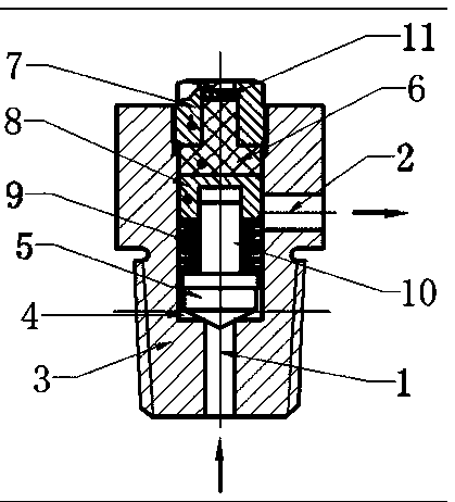
[0018] As shown in the figure, the high-pressure gas fusible alloy pressure relief device of the present invention includes a metal plug body 3 having a pressure relief inlet passage 1 and a pressure relief outlet passage 2, and the pressure relief inlet passage 1 is arranged at the bottom of the plug body and is connected with the container The inner cavity is connected, and the pressure relief outlet channel 3 is arranged on the side wall of the plug body. It can be seen from the figure that the pressure relief inlet channel 1 and the pressure relief outlet channel 2 are arranged at 90 degrees. The connection thread for connection, the connection thread section forms a base for installation with the container, the middle part of the plug body 3 has a component placement ca...


PUM


Abstract

The invention discloses a fusible-alloy pressure relief device for high pressure gas. The fusible-alloy pressure relief device comprises a cock body, a pressure relief inlet channel is formed in the bottom of the cock body, and a pressure relief outlet channel is formed in the side wall of the cock body. A component placement chamber is formed in the middle of the cock body and penetrates throughthe top of the cock body, and a sealing tip blocked at the pressure relief inlet channel and a fusible-alloy precast block are arranged in the component placement chamber. A press mounting piece witha central hole is arranged at the top of the cock body and is used for press-mounting the fusible-alloy precast block. The sealing tip can be pushed by medium pressure in the inner chamber of a container to extrude melt alloy liquid from the central hole of the press mounting piece, and meanwhile the pressure relief outlet channel is opened. The fusible-alloy pressure relief device has the advantages that a guide cap is pushed through the sealing tip and a disk spring to extrude the melt alloy liquid from the filter screen of the central hole of a pressing nut, and meanwhile the pressure relief channel is opened, thus the purpose of pressure relief is achieved, and the risk of failure of the fusible-alloy pressure relief device under normal operation is reduced.

Description

technical field [0001] The invention relates to a pressure relief device, in particular to a high-pressure gas fusible alloy pressure relief device. Background technique [0002] The traditionally used temperature-driven safety pressure relief device is to pour the fusible alloy directly into the hole of the metal plug body to form a whole "fusible alloy plug", which is placed on the pressure vessel such as the gas cylinder. When the temperature exceeds the flow temperature of the fusible alloy, the alloy begins to melt, and under the action of the medium pressure in the container, the plug body is directly extruded to form a through discharge channel to achieve the purpose of safe pressure relief. The traditionally used fusible alloy plug structure see figure 1 . [0003] Practice has shown that the existing fusible alloy plug with this structure produces a large thrust on the fusible alloy due to the high-pressure medium, while the strength of the fusible alloy itself is...

Claims


Application Information

Patent Timeline
IPC IPC(8): F16K17/40
CPCF16K17/40
Inventor 代德维李军英马夺刘文斌程飘张鹏赵蕾糜慧
Owner JIANGSU TIANHAI SPECIAL EQUIPMENT CO LTD
Learn More