
Hydraulic retarder and engine exhaust combined brake control method

A technology of hydraulic retarder and engine braking, which is applied in the direction of gear transmission mechanism, clutch, mechanical equipment, etc., can solve the problem of analyzing the working state of the hydraulic retarder of components, not considering or affecting the cooling system of the hydraulic retarder Service life and other issues, to meet the braking demand of the vehicle, reduce the difficulty of operation, and increase the maintenance cost.

Active Publication Date: 2018-08-24
SHENZHEN TERCA INFORMATION TECH
View PDF11 Cites 5 Cited by
  • Summary
  • Abstract
  • Description
  • Claims
  • Application Information

AI Technical Summary

Problems solved by technology

Its shortcomings are: 1) The control method only controls the work of the hydraulic retarder and exhaust brake by the body controller BCU according to the change of the vehicle speed, without specific analysis of the working state of the hydraulic retarder of the actuator, which may The hydraulic retarder is in an abnormal working state, such as overheating
2) Always give priority to the hydraulic retarder when braking, which will affect the service life of the hydraulic retarder and its cooling system
3) It is limited to constant speed cruise. In addition, the body controller BCU only controls how the hydraulic retarder and exhaust brake participate in the work, and does not consider how the hydraulic retarder and exhaust brake exit the system when the vehicle speed drops. moving problem

Method used


Image

  • Hydraulic retarder and engine exhaust combined brake control method
  • Hydraulic retarder and engine exhaust combined brake control method

Examples


Embodiment Construction

[0040] The present invention will be described in further detail below in conjunction with accompanying drawing:

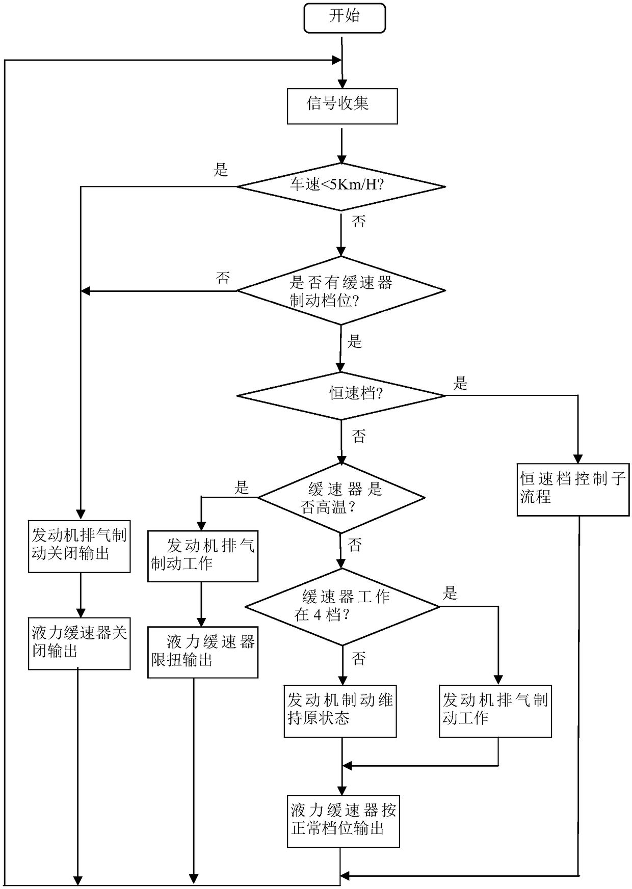
[0041] Such as figure 1 As shown, the control method of the combined braking of the hydraulic retarder and the exhaust of the engine includes the following steps:

[0042] ⑴ Carry out signal collection, collect signals through hardware circuit signal port or CAN bus, including gear position signal, vehicle speed signal, hydraulic retarder water temperature and oil temperature signal;

[0043] ⑵Judge whether the vehicle speed value is less than 5Km / h, if so, consider the vehicle speed is too low, turn off the output of the hydraulic retarder, turn off the output of the engine exhaust brake, return to step ⑴; if not, continue to judge whether there is a brake gear enter;

[0044] (3) Judging whether there is a brake gear input, if not, there is no torque request, the output of the hydraulic retarder is turned off, the output of the engine exhaust brake is turned o...


PUM


Abstract

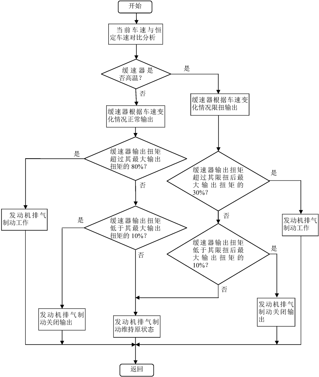
The invention relates to a hydraulic retarder and engine exhaust combined brake control method. The method comprises the steps that signals are collected through a signal port of a hardware circuit; whether the vehicle speed value is less than 5 Km / h or not is judged, and if yes, output of exhaust brake is closed; if not, whether brake gear input exists or not is judged, and if not, output of exhaust brake is closed; if yes, whether an input gear is a constant-speed gear or not is judged, and if yes, a constant-speed gear control sub-process is executed; if not, whether the retarder is at hightemperature or not is judged, and if yes, engine brake is started, and the retarder performs limited-torque output; if not, whether the retarder works at a highest gear, namely a fourth gear or not is judged, and if yes, the engine exhaust brake operation is started; if not, the engine exhaust brake is kept in an original state; the hydraulic retarder is output according to a normal gear; and thestep 1 is repeated, and the steps are carried out sequentially in a cyclic mode so as to form a control closed loop.

Description

technical field [0001] The invention relates to a control method in an automobile auxiliary braking system, in particular to a control method for combined braking of a hydraulic retarder and engine exhaust. Background technique [0002] CN201510028857.9 discloses a constant-speed cruise control system and method for an AMT vehicle based on a hydraulic retarder. The technical problem it solves is to improve the fuel economy of the whole vehicle under the premise of satisfying the power of the vehicle. Its technical scheme: the cruise control method of the AMT model based on the hydraulic retarder is as follows: (1) the instrument sends a cruise signal to the body controller BCU, and after the vehicle enters the cruise state, the body controller BCU saves the setting The fixed vehicle speed value, and monitor the current vehicle speed value; the current vehicle speed value is sent to the body controller BCU by the ABS in real time; (2) The vehicle body controller BCU compares...

Claims


Application Information

Patent Timeline
Patent Type & Authority Applications(China)
IPC IPC(8): F16D48/06
CPCF16D48/064F16D2121/18
Inventor 伍中权闻维维梅峰
Owner SHENZHEN TERCA INFORMATION TECH
Learn More