
Hydraulic cylinder

A hydraulic cylinder and cylinder block technology, applied in the field of hydraulic cylinders, can solve the problems of complex structure of punching machines, low transmission precision, low molding quality of products, and low stability of motion.

Active Publication Date: 2018-08-24
东莞市得力仕机械科技有限公司
View PDF8 Cites 2 Cited by
  • Summary
  • Abstract
  • Description
  • Claims
  • Application Information

AI Technical Summary

Problems solved by technology

However, the motor-driven method requires the use of flywheels, deceleration devices and other mechanisms, which will complicate the structure of the punching machine. In addition, this transmission method has the problems of relatively large transmission gap and relatively low motion stability. The transmission accuracy and product molding quality are low

Method used


Image

  • Hydraulic cylinder
  • Hydraulic cylinder
  • Hydraulic cylinder

Examples


Embodiment Construction

[0016] The technical solutions in the embodiments of the present invention will be clearly and completely described below in conjunction with the accompanying drawings. Apparently, the described embodiments are only part of the embodiments of the present invention, not all of them. Based on the embodiments of the present invention, all other embodiments obtained by persons of ordinary skill in the art without creative efforts fall within the protection scope of the present invention.

[0017] It should be noted that if the embodiment of the present invention involves directional indications (such as up, down, left, right, front, back, top, bottom, inside, outside, vertical, horizontal, vertical, counterclockwise, clockwise, circumferential direction, radial direction, axial direction...), the directional indication is only used to explain the relative positional relationship, movement conditions, etc. When a change occurs, the directional indication changes accordingly.

[00...


PUM


Abstract

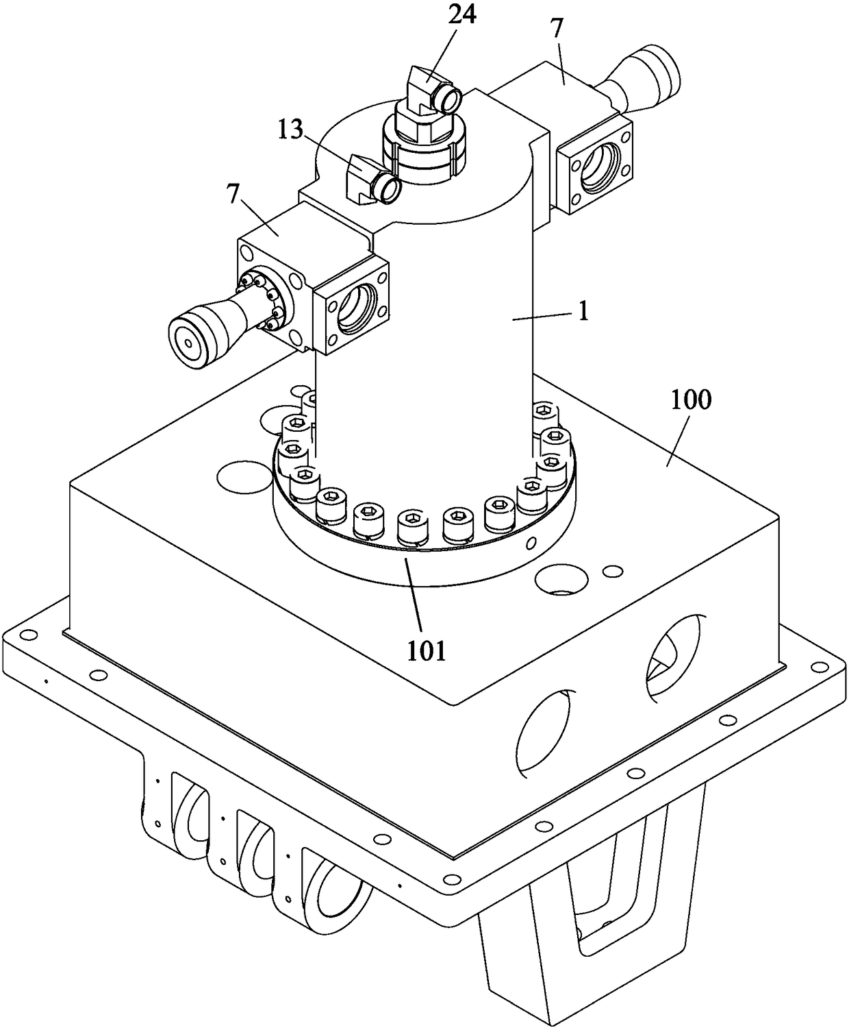
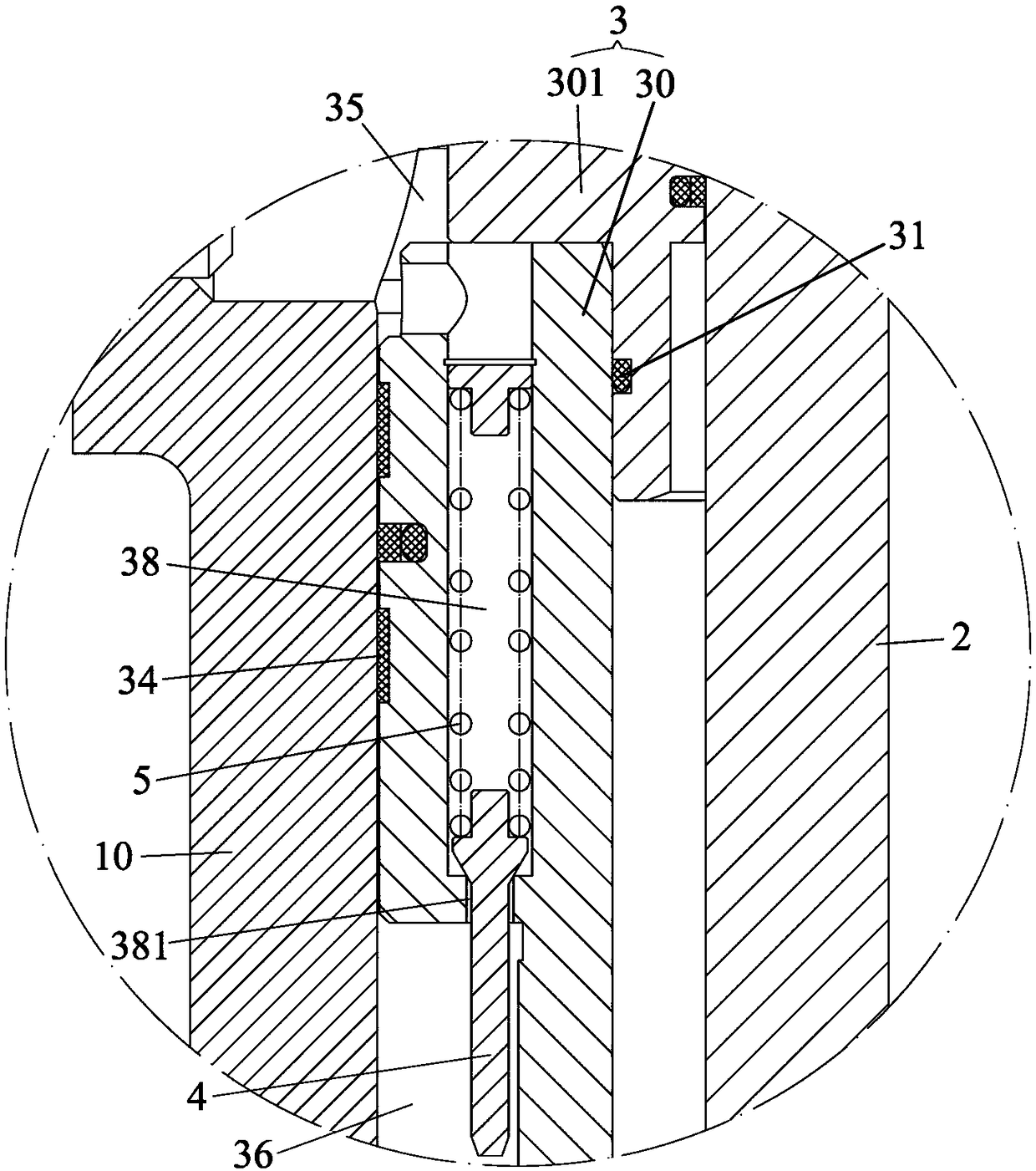
The invention discloses a hydraulic cylinder which comprises a cylinder block, an inner rod and a piston rod. Hydraulic oil with a first pressure is conveyed in a fast cavity through a fast liquid inlet pipe and a fast channel so as to drive the piston rod to fast extends out within the displacement range needing to fast extend out. Hydraulic oil with a second pressure is conveyed in a pressing cavity through a pressing channel and a pressing liquid inlet pipe to fast increase the output thrust of the piston rod and enable the piston rod to extend out slowly. When the piston rod is about to completely extend out, a valve element moves along with the piston rod to be propped against the bottom wall of the inner side of the cylinder block, and the valve element overcomes the elastic force ofan ejecting spring to move upwards under the resistance of the bottom wall of the inner side of the cylinder block and open a pressure relief hole. The hydraulic oil with the second pressure in the pressing cavity flows into a pressure relief cavity through a transition cavity and the pressure relief hole to fast reduce the thrust to the piston rod automatically and omit the pressure relief timeof an electrical system and a hydraulic system. When the hydraulic cylinder is applied to a punching machine, the punching efficiency can be improved, the structure of the punching machine is simplified, and the corresponding transmission precision is improved.

Description

technical field [0001] The invention relates to the technical field of hydraulic transmission, in particular to a hydraulic cylinder. Background technique [0002] The hydraulic cylinder is the actuator in the hydraulic transmission system, and it is an energy conversion device that converts hydraulic energy into mechanical energy. It has the characteristics of simple structure and reliable operation. When it is used to realize linear reciprocating motion, the deceleration device can be eliminated, and there is no transmission gap, the movement is stable, and the transmission accuracy is high. Therefore, it is widely used in various mechanical hydraulic systems. [0003] However, the existing hydraulic cylinders are affected by the slow switching of the output speed value and thrust value, and the scope of use is limited. For example, for a stamping machine, it is required to be able to drive the upper die Provide different speeds and thrusts for the upper mold in different...

Claims


Application Information

Patent Timeline
IPC IPC(8): F15B15/14F15B15/20F15B15/22
CPCF15B15/1447F15B15/1457F15B15/1461F15B15/20F15B15/221
Inventor 陈启文唐文英
Owner 东莞市得力仕机械科技有限公司
Learn More