
Composite rotor flying car

A technology of flying cars and cars, applied in the field of composite rotor flying cars, can solve the problems of low flying rate, low safety performance, and large occupied space, and achieve the effect of increasing safety performance and being suitable for popularization and use

Inactive Publication Date: 2018-08-24
FOSHAN SHENFENG AVIATION SCI & TECH
View PDF0 Cites 1 Cited by
  • Summary
  • Abstract
  • Description
  • Claims
  • Application Information

AI Technical Summary

Problems solved by technology

[0005] In view of this, the present invention provides a compound rotor flying car to overcome the problems of the compound rotor flying car in the prior art that occupy a large space, have a low rate of lift and have low safety performance

Method used


Image

  • Composite rotor flying car

Examples


Embodiment Construction

[0022] The following will clearly and completely describe the technical solutions in the embodiments of the present invention with reference to the accompanying drawings in the embodiments of the present invention. Obviously, the described embodiments are only some, not all, embodiments of the present invention. Based on the embodiments of the present invention, all other embodiments obtained by persons of ordinary skill in the art without making creative efforts belong to the protection scope of the present invention.

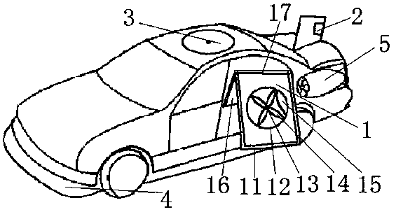
[0023] The embodiment of the present invention discloses a compound rotor flying car, including a car, wherein a compound rotor 1 is provided at the middle of both sides of the car body, and the angle between the compound rotor 1 and the horizontal plane of the car body is between 10° and 20°. at the rear position of the car body; a parachute cabin 3 is installed on the top of the car body; a floating body 4, a motor and an inflation pipeline are arranged on th...


PUM


Abstract

The invention discloses a composite rotor flying car. The composite rotor flying car includes a car, wherein composite rotors are arranged at the intermediate positions of two side surfaces of a car body of the car, and included angles between the composite rotors and a horizontal plane of the car body of the car are between 10-20 degrees. A rudder is arranged at the rear side position of the carbody of the car. A parachute bay is installed at the top of the car body of the car. A floating body, an electric motor and an inflation pipe are arranged on a chassis of the car. The floating body and the electric motor are connected through the inflation pipe. A jet engine is arranged at the rear side position of the side surface of the car body of the car, and the jet engine can be rotatably retracted into a trunk of the car. According to the technical scheme, the problem that a composite rotor flying car in the prior art is large in occupied space area, low in flying rising rate and low insafety performance is solved.

Description

technical field [0001] The invention relates to the technical field of vehicles, and more specifically relates to a composite rotor flying vehicle. Background technique [0002] At present, as a means of transportation and transportation in modern society, automobiles play an irreplaceable role in today's society; however, with the development of society and the increase of automobiles, our roads are becoming more and more congested; now , many countries, companies, collectives and individuals are all looking to the sky, hoping to invent a flying car that can have both the functions of a car and an airplane, that is, flying in the air or driving on land, transforming from a road car As an aircraft, in order to solve the problem of human travel and road congestion. [0003] However, the existing compound rotor flying vehicles occupy a large space, have a low rate of ascent, and need to be strengthened in safety performance, so they have not been widely popularized and used o...

Claims


Application Information

Patent Timeline
Patent Type & Authority Applications(China)
IPC IPC(8): B60F5/02
CPCB60F5/02
Inventor 王志成
Owner FOSHAN SHENFENG AVIATION SCI & TECH
Learn More