Transmission device integrating dynamic brake and planetary reducer

A planetary reducer and dynamic brake technology, applied in transmission parts, brake types, axial brakes, etc., can solve problems such as brake wear and tear, and achieve the effects of reducing speed, sufficient lubrication, and prolonging service life.

Inactive Publication Date: 2018-08-21
INI HYDRAULIC
View PDF6 Cites 1 Cited by
  • Summary
  • Abstract
  • Description
  • Claims
  • Application Information

AI Technical Summary

Problems solved by technology

[0004] The invention provides a dynamic brake and planetary reducer integrated transmission device with ingenious structure, compact, safe, reliable and long service life, which solves the problem of serious brake loss when the main body speed of the hydraulic motor is high

Method used


Image

  • Transmission device integrating dynamic brake and planetary reducer

Examples


Embodiment Construction

[0021] The present invention will be further described in detail below in conjunction with the accompanying drawings and examples. The following examples are explanations of the present invention and the present invention is not limited to the following examples.

[0022] Example.

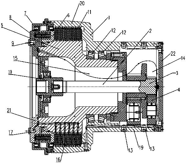
[0023] see figure 1 , a transmission device integrating a dynamic brake and a planetary reducer, including a casing assembly 1 integrally formed by a planetary reducer casing 19 and a brake casing 20, a planetary reducer assembly, a brake, and a power input shaft 2. The housing assembly 1 is provided with a working inner cavity passing through the left and right ends. The planetary reducer assembly, the brake and the power input shaft 2 are all located in the working cavity of the housing assembly 1 .

[0024] The outer dimensions of the brake housing 20 are larger than the outer dimensions of the planetary reducer housing 19, so the brake working cavity in the brake housing 20 is larger than the...


PUM


Abstract

The invention provides a transmission device integrating a dynamic brake and a planetary reducer. The transmission device integrating the dynamic brake and the planetary reducer has the advantages ofbeing ingenious and compact in structure, safe, reliable and long in service life. The transmission device comprises a shell assembly, a power input shaft, a sun gear, a planetary gear, a planetary carrier and the brake, wherein the power input shaft is arranged in the shell assembly, the sun gear sleeves the power input shaft, the planetary gear is arranged between the sun gear and the inner wallof the shell assembly, the planetary carrier is fixedly arranged on a shell assembly joint, and the brake is used for braking the shell assembly.

Description

technical field [0001] The invention relates to a brake technology, in particular to a transmission device in which a dynamic brake and a planetary reducer are integrated. Background technique [0002] At present, the planetary reducer braking device for construction machinery and mining machinery is often used for vehicle parking braking (static braking), and the braking function is realized through the braking power source (hydraulic motor, electric motor, etc.), which often limits the power The speed of the source (if it is used for dynamic braking, too fast speed will cause the friction plate to heat up too fast, it is difficult to achieve dynamic balance, and it will easily lead to overheating and aging of the internal seal, and it will have a great impact on the bearing and internal parts. The wear resistance of the parts is greatly reduced), thus limiting the working speed. At present, the requirements for the reducer used in engineering vehicles and mining vehicles i...

Claims


Application Information

Patent Timeline
IPC IPC(8): F16H57/023F16H57/04F16H57/029F16D55/226F16D121/04
CPCF16H57/023F16D55/226F16D2121/04F16H57/029F16H57/042
Inventor 胡世璇
Owner INI HYDRAULIC
Why Eureka
Try Eureka