
Gas pipe-expanding machine for condenser copper pipe

A technology of a tube expander and a condenser, which is applied to the feeding device, positioning device, storage device, etc., can solve the problems of inconsistent length of legs, cracked copper tube ends, and inability to adjust, and achieves ingenious conception, convenient use, and structure. simple effect

Pending Publication Date: 2018-08-21
广州市通上德机电设备有限公司
View PDF3 Cites 1 Cited by
  • Summary
  • Abstract
  • Description
  • Claims
  • Application Information

AI Technical Summary

Problems solved by technology

This requires arranging different workstations in the workshop and arranging corresponding operators, which is not conducive to the control of production costs and the improvement of production efficiency
[0004] In addition, the existing cup opening and bell opening are completed in one step using integral tooling, and the position of the cup mouth and bell mouth of the overall tooling is fixed and cannot be adjusted
However, in actual production, it is impossible to ensure that the heights of the ends of the copper pipes are consistent. Often, the lengths of the upper ends of the copper pipes to be expanded and the bell mouths are inconsistent.
When the overall tooling is used for one-time expansion, the stroke of the tooling is difficult to set. If the tooling goes down more, the higher end of the copper pipe is prone to cracking; situation, resulting in a large number of defective products, which is further detrimental to cost control and improvement of production efficiency

Method used

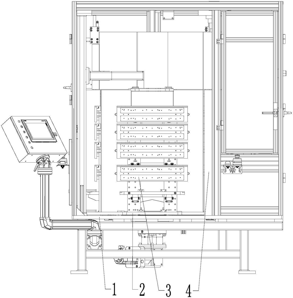
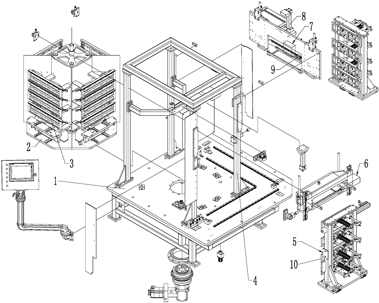
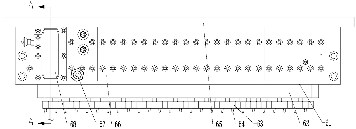

Image

  • Gas pipe-expanding machine for condenser copper pipe
  • Gas pipe-expanding machine for condenser copper pipe
  • Gas pipe-expanding machine for condenser copper pipe

Examples


Embodiment Construction

[0030] Embodiments of the technical solutions of the present invention will be described in detail below in conjunction with the accompanying drawings. The following examples are only used to illustrate the technical solutions of the present invention more clearly, and therefore are only examples, rather than limiting the protection scope of the present invention.

[0031] In the description of the present application, it should be understood that the terms "center", "longitudinal", "transverse", "length", "width", "thickness", "upper", "lower", "front", " Back", "Left", "Right", "Vertical", "Horizontal", "Top", "Bottom", "Inner", "Outer", "Clockwise", "Counterclockwise", "Axial", The orientation or positional relationship indicated by "radial", "circumferential", etc. is based on the orientation or positional relationship shown in the drawings, and is only for the convenience of describing the present invention and simplifying the description, rather than indicating or implyi...


PUM


Abstract

The invention discloses a gas pipe-expanding machine for a condenser copper pipe. The machine includes a working table, four working positions are evenly distributed on the working table in the circumferential direction, and a pipe expanding tool and a flaring tool are installed on the two adjacent working positions of the four working positions respectively; the working table is further providedwith a rotary plate, four limiting tools are evenly distributed on the rotary plate in the circumferential direction, the rotary plate is further connected with a rotation driving device, and under the action of the rotation driving device, the rotary plate rotates in the circumferential direction to make each limiting tool switched to the corresponding working position sequentially. When in actual use, another working position next to the working position where the pipe expanding tool is located is a material loading working position, another working position next to the working position where the flaring tool is located is a material unloading working position, the working positions where the pipe expanding tool and the flaring tool are located are a pipe expanding working position and aflaring working position respectively, only one operator needs to be arranged to the material loading working position and the material unloading working position separately, therefore, the pipe expanding and flaring efficiency of the condenser copper pipe is remarkably improved, the labor cost is greatly reduced, and the whole machine is compact in structure, small in occupied space and favorable for workshop layout.

Description

technical field [0001] The invention belongs to the technical field of condenser production equipment, and in particular relates to a gas tube expander for condenser copper tube expansion. Background technique [0002] At present, when the condenser is processed, it is necessary to expand the copper tube to eliminate the gap between the copper tube and the fins. The traditional tube expansion process uses mechanical tube expansion, which requires the expansion rod to be inserted into the copper tube. There are many problems. For example, the expansion rod will cause damage to the internal thread of the copper tube, and the lubricating oil of the expansion rod will cause trouble in cleaning the inside of the copper tube. Aiming at the shortcomings of mechanical tube expansion, a new process of hydraulic tube expansion method has been produced, but the hydraulic tube expansion method also has the problem of troublesome cleaning in the copper tube. Therefore, there are also th...

Claims


Application Information

Patent Timeline
IPC IPC(8): B21D39/20B21D41/02B21D53/06B21D43/14B21D43/00
CPCB21D39/203B21D41/028B21D43/003B21D43/14B21D53/06
Inventor 洛奇·史密斯戴北平
Owner 广州市通上德机电设备有限公司
Learn More