A direction-finding system and method for broadband chirp signals based on time modulation
A technology of linear frequency modulation signal and time modulation, which is applied in the direction of frequency modulation carrier system, modulated carrier system, radio wave measurement system, etc. It can solve the problems of bandwidth modulation frequency limitation of incoming wave signal, and achieve the effect of saving cost and reducing complexity
- Summary
- Abstract
- Description
- Claims
- Application Information
AI Technical Summary
Problems solved by technology
Method used
Image
Examples
Embodiment
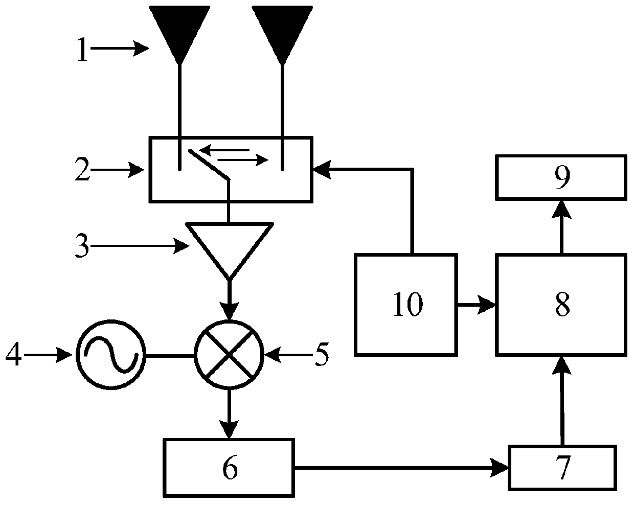
[0050] This embodiment provides a broadband chirp signal direction finding system based on time modulation, including an antenna array module, a radio frequency switch module, a radio frequency receiving channel module, a time-frequency signal processing module, an output display module and a digital control module, wherein the radio frequency receiving The channel module includes a low-noise amplifier 3 , a mixer 4 , a radio frequency local oscillator unit 5 , a low-pass filter 6 and an analog-to-digital converter 7 . The printed dipole antenna array unit 1 of the antenna array module is connected with the single pole double throw switch (high-speed radio frequency switch) 2 of the radio frequency switch module, and the single pole double throw switch is connected with a low noise amplifier, and the low noise amplifier Connected with the mixer, the mixer is respectively connected with the radio frequency local oscillator and the low-pass filter, the low-pass filter is connecte...
example
[0063] Example, Wideband Chirp Signal Direction Finding
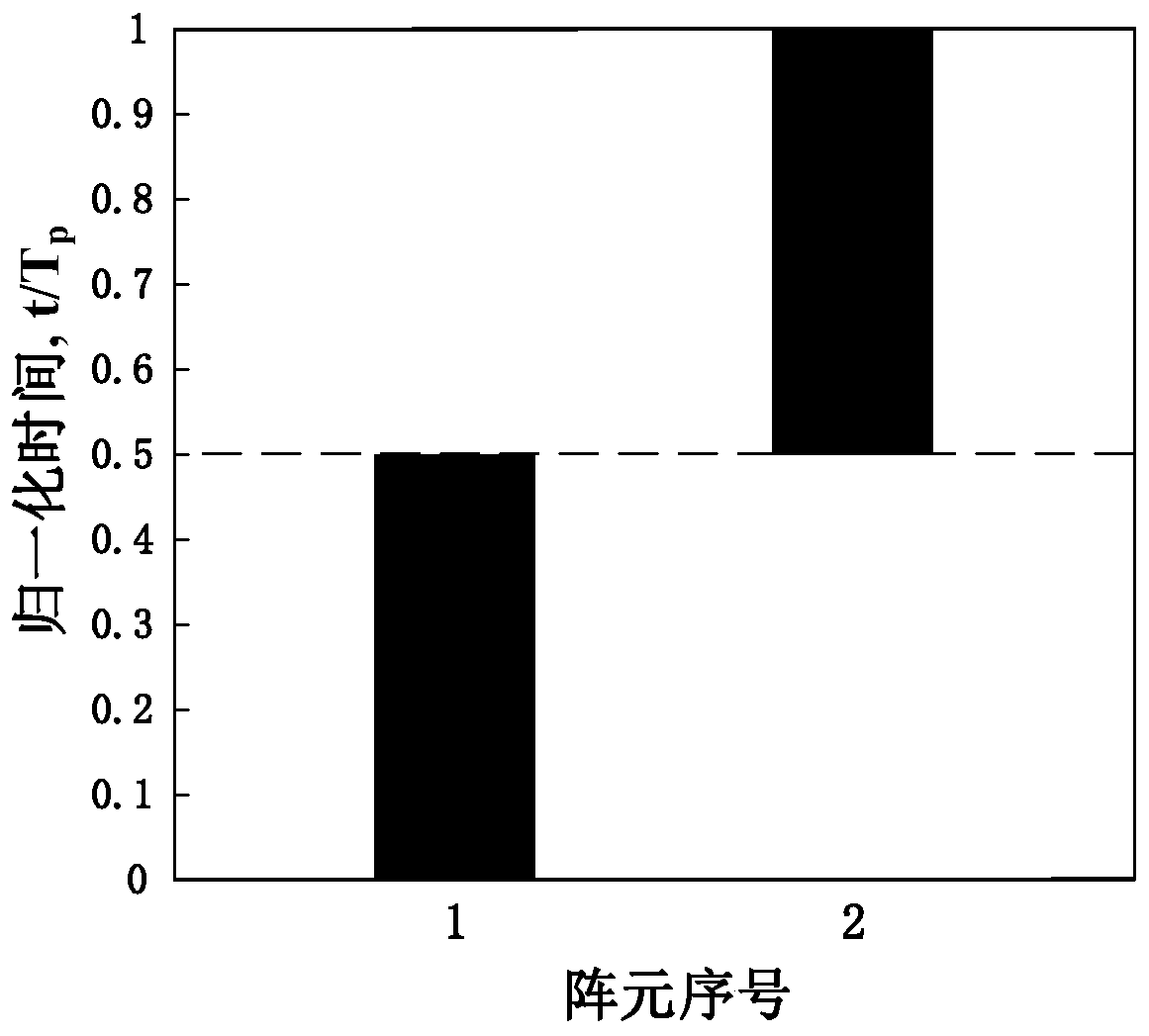
[0064] When the carrier frequency is f 0 =2GHz, the bandwidth is B=20MHz, and the chirp signal with duration T=200μs is at an azimuth angle of 15 ° When incident on the antenna array module, the antenna array element spacing (i.e. array element spacing) d=λ / 2=15cm, λ=c / f 0 is the wavelength of the incident signal, c is the propagation speed of electromagnetic waves in vacuum, and the timing diagram of the periodic opening and closing of the radio frequency switch module is shown in figure 2 As shown, its modulation period is T p = 1μs, modulation frequency f p = 1MHz, in one modulation period, the turn-on time of each antenna array unit is 0.5μs, the number of sub-band signals divided by the whole chirp signal M=T / T p =200.
[0065] image 3 The time-domain waveforms of the modulated timing signal (a), the incident linear FM signal (b) and the modulated linear FM signal (c) modulated by the RF switch are given re...
PUM
 Abstract
Description
Claims
Application Information
 - R&D
- Intellectual Property
- Life Sciences
- Materials
- Tech Scout
- Unparalleled Data Quality
- Higher Quality Content
- 60% Fewer Hallucinations
Browse by: Latest US Patents, China's latest patents, Technical Efficacy Thesaurus, Application Domain, Technology Topic, Popular Technical Reports.
© 2025 PatSnap. All rights reserved.Legal|Privacy policy|Modern Slavery Act Transparency Statement|Sitemap|About US| Contact US: help@patsnap.com


