
Intelligent agricultural water-saving valve

A valve and agricultural technology, applied in the field of intelligent agricultural water-saving valves, can solve problems such as inability to effectively control water flow in and out, complex structure, and failure to meet market demand.

Pending Publication Date: 2018-08-17
如皋市农田水利试验站 +1
View PDF0 Cites 5 Cited by
  • Summary
  • Abstract
  • Description
  • Claims
  • Application Information

AI Technical Summary

Problems solved by technology

At present, in rural areas, the phenomenon of agricultural water waste is very common. Because the water in the farmland needs to be managed by people, the water must be boiled when it comes, and the water must be turned off by people when it is full, which is very troublesome.
Generally, self-control valves are used to realize brake control, but the existing valve switches are not sensitive and cannot effectively control the water flow in and out. High cost, complex structure, uneconomical, unable to meet market demand

Method used


Image

  • Intelligent agricultural water-saving valve
  • Intelligent agricultural water-saving valve
  • Intelligent agricultural water-saving valve

Examples


Embodiment 1

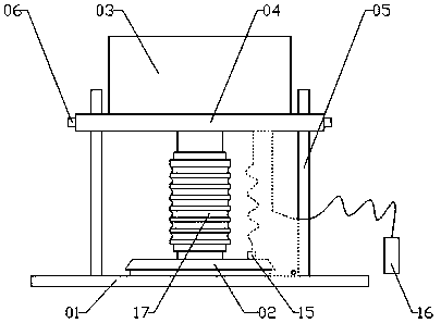
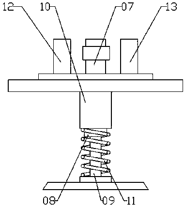
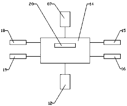
[0020] Such as Figure 1-3 As shown, an intelligent agricultural water-saving valve includes a valve seat 01, a valve cover 02 and a valve chamber 03, a fixed plate 04 is arranged in parallel above the valve seat 01, and a round hole is opened in the middle of the valve seat 01. A number of guide posts 05 are evenly arranged on the outer circumference of the valve seat hole, one end of the guide post is fixedly connected to the valve seat 01, and the other end protrudes through the fixed plate 04, and a guide sleeve is arranged between the fixed plate 04 and the guide post 05, and the guide sleeve is fixed. On the fixed plate, it is slidingly connected with the guide post 05, and the side walls of the fixed plate 04 are respectively provided with positioning bolts 06 corresponding to the positions of the guide post 05. Connect the fixed plate 04 and the guide post 05, the fixed plate 04 moves up and down along the direction of the guide post 05, and adjust the distance between...

Embodiment 2

[0022] Such as Figure 1-2 As shown, further improvements are made on the basis of the embodiment, the upper limit switch 18 and the lower limit switch 19 are removed, and the time program of the time-controlled motor is installed in the controller chip; the controller 13 controls the motor 07 to drive the valve cover 02 to move upward , when the upper limit setting time of the time program is reached, the controller 13 controls to stop the motor 07, the valve cover is at the upper limit, the controller 13 controls the motor 07 to drive the valve cover 02 to move down, and when the time program lower limit setting time is reached, the controller 13 controls Stop motor 07, valve cover 02 is in lower limit.


PUM


Abstract

The invention relates to an intelligent agricultural water-saving valve. The intelligent agricultural water-saving valve comprises a valve seat, a valve cover and a valve chamber, wherein a fixed plate is arranged above the valve seat in parallel; a circular hole is formed in the middle of the valve seat; a plurality of supporting posts are uniformly arranged at the periphery of the circular holeof the valve seat; the supporting posts are fixedly connected with the valve seat and the fixed plate; the valve chamber is arranged on the fixed plate; a drive device is arranged in the valve chamber; the drive device sequentially passes through the bottom of the valve chamber and the fixed plate, and is connected with the valve cover; the valve cover is positioned above the circular hole of thevalve seat; a battery and a controller are further arranged in the valve chamber; the valve cover is in sealing contact with the valve seat; when the valve cover is positioned on a lower limiting position, the valve is closed and the valve cover is separated from the valve seat; and when the valve cover is positioned on an upper limiting position, the valve is opened. The intelligent agriculturalwater-saving valve is reasonable in design, is simple in structure, can automatically control opening / closing of the valve according to water level of a farmland, performs farmland water level regulation, and avoids water resource loss as a result of unmanned management of farmland irrigation, so that farmland irrigation water is greatly saved.

Description

[0001] technology niche [0002] The invention relates to the field of agricultural irrigation, in particular to an intelligent agricultural water-saving valve. Background technique [0003] According to statistics, my country's agricultural irrigation water consumption accounts for 80% of the country's total water consumption, while rice field irrigation water consumption accounts for 65% of agricultural water consumption. At present, in rural areas, the phenomenon of wasting agricultural water is very common. Because the water in the farmland needs to be managed by people, the water must be boiled when it comes, and the water must be turned off by people when it is full, which is very troublesome. Generally, self-control valves are used to realize brake control, but the existing valve switches are not sensitive and cannot effectively control the water flow in and out. The cost is high, the structure is complex, uneconomical, and cannot meet market demand. Contents of the ...

Claims


Application Information

Patent Timeline
IPC IPC(8): F16K31/04F16K37/00F16K51/00
CPCF16K31/04F16K37/0025F16K51/00
Inventor 肖海涛汤宝田何风平
Owner 如皋市农田水利试验站
Learn More