
In-hole micro difference blasting method performing punching in upward direction of medium-deep hole and explosive charging in downward direction of medium-deep hole

A micro-blasting and deep-hole technology, which is applied in blasting, earthwork drilling, discharge machinery, etc., to achieve safe and reliable construction, overcome complex operations, and ensure the effect of blasting

Active Publication Date: 2018-08-14
CHANGCHUN GOLD RES INST
View PDF5 Cites 4 Cited by
  • Summary
  • Abstract
  • Description
  • Claims
  • Application Information

AI Technical Summary

Problems solved by technology

[0003] In order to overcome the above-mentioned problems, the present invention provides a micro-differential blasting method in the middle and deep holes, which is drilled upwards and charged downwards. By drilling upwards in the lower section, after connecting with the upper section, and then from the upper section to the Bottom charge, there is a corresponding working space in the upper and lower sections, to solve the technical problem of realizing micro-difference blasting in the medium and deep hole blasting operation in the mine, through this method, the middle and deep holes can be drilled upward and charged downward Micro-differential blasting in the hole, in the blasting of medium and deep holes, it not only improves the charge efficiency, but also ensures the blasting effect, ensuring the success of blasting into the well

Method used


Image

  • In-hole micro difference blasting method performing punching in upward direction of medium-deep hole and explosive charging in downward direction of medium-deep hole
  • In-hole micro difference blasting method performing punching in upward direction of medium-deep hole and explosive charging in downward direction of medium-deep hole
  • In-hole micro difference blasting method performing punching in upward direction of medium-deep hole and explosive charging in downward direction of medium-deep hole

Examples


Embodiment Construction

[0024] The present invention will be further described below in conjunction with the accompanying drawings.

[0025] A method of in-hole micro-difference blasting in which the hole is drilled upwards and charged downwards in a medium-deep hole, such as figure 1 As shown, the specific operation steps are as follows:

[0026] Step 1: Drill upward blastholes, that is, medium-depth holes 1. During the drilling process, ensure that the blastholes are vertical and control the deflection rate of the blastholes;

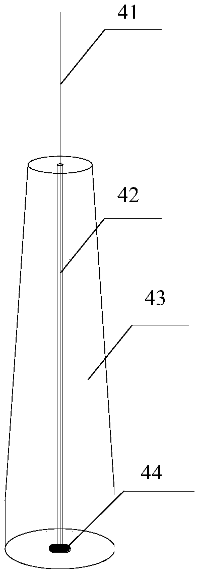
[0027] Step 2: If figure 2 Shown, make blasthole orifice plug 4, and blasthole orifice plug 4 is the conical cork 43 that is made of cork, and the center of conical cork 43 is drilled with steel wire perforation 42, and conical cork 43 bottom The center is provided with a retaining ring 44 at the center of the steel wire perforation 42;

[0028] Step 3: Insert the hole plug 4 of the blast hole into the lower opening of the middle-deep hole 1, and plug it tightly, lower t...


PUM


Abstract

The invention belongs to the technical field of metal mines and particularly relates to an in-hole micro difference blasting method performing punching in the upward direction of a medium-deep hole and explosive charging in the downward direction of the medium-deep hole. The medium-deep hole is drilled from a lower segment to an upper segment, and communicating with the upper segment is achieved;a blast hole port plug is plugged in a lower hole of a blast hole, blocking stemming is contained in, and hole plugging of a lower hole port is completed; due to the method that a plurality of segments of detonating bombs and bulk explosive are arranged in the blast hole, and the plugging stemming is used in the blast hole to perform multi-segment blasting, the technical problem for achieving in-hole micro difference blasting during medium-deep hole blasting operation under a mine is solved; by means of the method, in-hole micro difference blasting with punching in the upward direction of themedium-deep hole and explosive charging in the downward direction of the medium-deep hole can be achieved, in medium-deep hole blasting simultaneous shaft-sinking, the explosive charging efficiency isimproved, the blasting effect is also guaranteed, and successful blasting shaft-sinking is guaranteed.

Description

technical field [0001] The invention belongs to the technical field of metal mines, and in particular relates to an in-hole micro-difference blasting method for drilling upwards and downwards for middle and deep holes. Background technique [0002] In the field of metal mining, medium and deep hole blasting technology has been widely used, and it is mainly used in the stope mining of thick and large ore bodies. At present, more and more mines adopt medium and deep hole blasting one-time well-forming technology in the excavation of the raised shaft. It is difficult to realize the micro-differential blasting in the hole in the blasting of the upward hole. powder, or fix the powder coil on the bamboo pole and send it to the blasthole to realize the charge at intervals in the hole, but the effect is not ideal in the actual blasting. Moreover, it will also affect the blasting effect, damage the surrounding blastholes, and cause serious over- and under-excavation phenomena; if th...

Claims


Application Information

Patent Timeline
Patent Type & Authority Applications(China)
IPC IPC(8): F42D1/08F42D1/10F42D1/18F42D1/04F42D3/04E21C37/00
CPCE21C37/00F42D1/04F42D1/08F42D1/10F42D1/18F42D3/04
Inventor 姜永恒宋士生闵忠鹏唐学义任玉东刘龙琼汪志国
Owner CHANGCHUN GOLD RES INST
Learn More