Rapid response temperature measuring thermocouple for metal mold casting

A temperature measurement thermocouple, metal mold casting technology, applied in the direction of measuring heat, thermometers, measuring devices, etc., can solve the problems of slow response of armored thermocouples, unable to meet the requirements of temperature measurement and temperature control, etc. Large contact area, the effect of avoiding contamination

Active Publication Date: 2018-08-10
BEIHANG UNIV
View PDF11 Cites 2 Cited by
  • Summary
  • Abstract
  • Description
  • Claims
  • Application Information

AI Technical Summary

Problems solved by technology

At present, the thermocouple used for industrial temperature measurement has a basic structure including thermocouple wire, insulating tube, protection tube and junction box. The wire is installed in a sealed sleeve filled with insulating material. When measuring, the outer end of the sleeve is usually equipped with a protective tube. The front part of the metal sleeve is in contact with the measured object. When the temperature of the measured object is higher than the temperature of the metal sleeve, the heat is taken The measured object-sleeve-insulating material (or air)-temperature-measuring node conducts sequentially, so that the temperature-measuring node reaches the same temperature as the measured object, and then performs measurement. During this process, due to the heat passing through the metal sleeve and The insulating material (or air) takes a certain amount of time, especially the thermal conductivity of the insulating material or air is very low, so the existing armored thermocouple responds slowly. According to the literature, the traditional thermocouple usually responds within 10 More than seconds, unable to meet the temperature measurement and temperature control requirements of modern foundry production

Method used


Image

  • Rapid response temperature measuring thermocouple for metal mold casting

Examples


Embodiment Construction

[0017] The present invention will be further described below in conjunction with the accompanying drawings and specific embodiments.

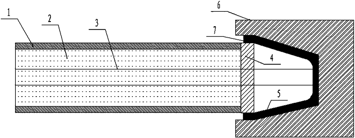
[0018] The fast-response thermocouple disclosed in the present invention includes two thermocouple wires 3, the materials used for the two thermocouple wires are NiCr alloy and NiSi alloy respectively, the thermocouple wires are located in the protective sleeve 1, and the sleeve is filled with insulating material 2, The two thermocouple wires are connected by a metal joint 5 at the hot end, and there is an insulating pad 4 between the metal joint and the casing.

[0019] When measuring temperature, such as measuring the temperature of an aluminum alloy low-pressure casting mold, the metal joint is directly inserted into the temperature measuring hole of the mold 6 to contact the mold wall. During temperature measurement, the heat is directly transmitted to the metal joint through the mold wall. At this time, the metal joint The contact point wi...


PUM


Abstract

The invention discloses a rapid response temperature measuring thermocouple for metal mold casting, comprising two thermocouple wires, which are arranged in a protective sleeve and connected by a metal joint at a hot end. The metal joint is a truncated cone structure, the longitudinal section is trapezoidal, and the center of the trapezoid is a hollow structure. A part, contacted with a mold temperature measuring hole, of the metal joint is a smooth plane, and the contact surface of the mold temperature measuring hole corresponding to the metal joint is also processed into a smooth plane; andbehind the metal joint, a high temperature sealant is arranged between the inner wall of the temperature measuring hole and the protective sleeve. The rapid response temperature measuring thermocouplerapidly transfers heat of the mold after the temperature rise to the thermocouple, and realizes the rapid response of the thermocouple to the temperature. The smooth contact surface of the metal joint of the thermocouple is protected from environmental influences. The metal joint is insulated from thermocouple parts other than the thermocouple wires so as to avoid interference.

Description

technical field [0001] The invention belongs to the technical field of casting equipment, and in particular relates to a fast-response temperature-measuring thermocouple for metal mold casting, which is used for measuring the mold temperature in the metal mold casting process. Background technique [0002] Thermocouple is a commonly used temperature measuring element in temperature measuring instruments. The basic principle of thermocouple temperature measurement is that two material conductors with different components form a closed loop. When there is a temperature gradient at both ends, current will flow through the loop. At this time There is a measurable thermal emf between the two ends. Two homogeneous conductors with different components are thermal electrodes, the end with higher temperature is the working end, or measuring end, hot end, and the end with lower temperature is free end, or reference end, cold end. According to the functional relationship between therm...

Claims


Application Information

Patent Timeline
IPC IPC(8): G01K7/02G01K1/08G01K1/14G01K1/16
CPCG01K1/08G01K1/143G01K1/146G01K1/16G01K7/023
Inventor 张花蕊张虎
Owner BEIHANG UNIV
Why Eureka
Try Eureka