Waste oil recycling method of capacitor aluminum shell punching oil
A technology for stamping oil and capacitors, which is applied in chemical instruments and methods, semi-permeable membrane separation, and sediment separation by centrifugal force. strong effect
- Summary
- Abstract
- Description
- Claims
- Application Information
AI Technical Summary
Problems solved by technology
Method used
Image
Examples
Embodiment 1
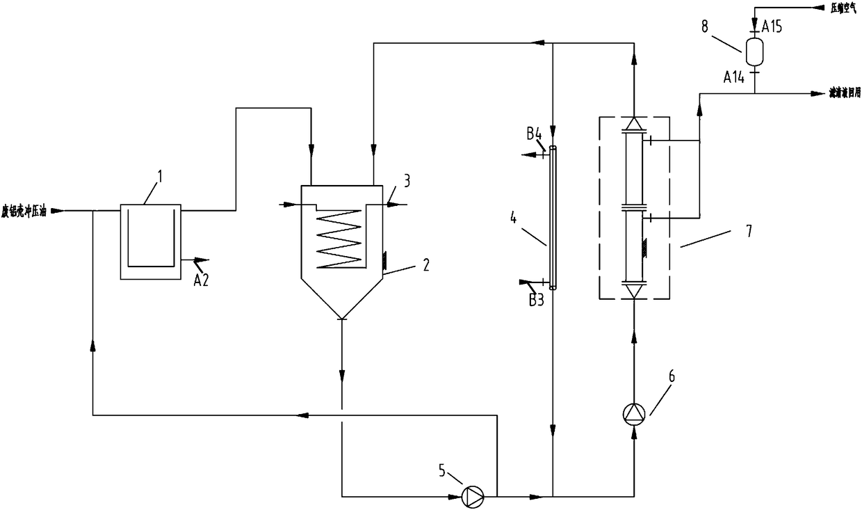
[0036] like figure 1 As shown in the figure, a waste oil recovery device for aluminum casing stamping oil of capacitors includes: a high-speed centrifuge 1, a raw material tank 2, a heating coil 3, a temperature control jacket 4, a feeding pump 5, a circulating pump 6, a Flow circulation group 7 and isolation backflush tank 8.
[0037]The high-speed centrifuge, the raw material tank, the feeding pump, the circulation pump, and the cross-flow circulation group are connected in sequence, and the two ends of the temperature control jacket are respectively connected with the two ends of the cross-flow circulation group to form a circulation loop; the cross-flow circulation The concentrated oil in the group passes through the raw material tank and the feed pump in turn and returns to the high-speed centrifuge; the heating coil is set on the raw material tank, and the isolation backflush tank is set on the filtered oil outlet of the cross-flow circulation group .
[0038] Wherein,...
Embodiment 2
[0047] like figure 1 As shown in the figure, a waste oil recovery device for aluminum casing stamping oil of capacitors includes: a high-speed centrifuge 1, a raw material tank 2, a heating coil 3, a temperature control jacket 4, a feeding pump 5, a circulating pump 6, a Flow circulation group 7 and isolation backflush tank 8.
[0048] The high-speed centrifuge, the raw material tank, the feeding pump, the circulation pump, and the cross-flow circulation group are connected in sequence, and the two ends of the temperature control jacket are respectively connected with the two ends of the cross-flow circulation group to form a circulation loop; the cross-flow circulation The concentrated oil in the group passes through the raw material tank and the feed pump in turn and returns to the high-speed centrifuge; the heating coil is set on the raw material tank, and the isolation backflush tank is set on the filtered oil outlet of the cross-flow circulation group .
[0049] Wherein...
Embodiment 3
[0058] like figure 1 As shown in the figure, a waste oil recovery device for aluminum casing stamping oil of capacitors includes: a high-speed centrifuge 1, a raw material tank 2, a heating coil 3, a temperature control jacket 4, a feeding pump 5, a circulating pump 6, a Flow circulation group 7 and isolation backflush tank 8.
[0059] The high-speed centrifuge, the raw material tank, the feeding pump, the circulation pump, and the cross-flow circulation group are connected in sequence, and the two ends of the temperature control jacket are respectively connected with the two ends of the cross-flow circulation group to form a circulation loop; the cross-flow circulation The concentrated oil in the group passes through the raw material tank and the feed pump in turn and returns to the high-speed centrifuge; the heating coil is set on the raw material tank, and the isolation backflush tank is set on the filtered oil outlet of the cross-flow circulation group .
[0060] Wherein...
PUM
| Property | Measurement | Unit |
|---|---|---|
| pore size | aaaaa | aaaaa |
| diameter | aaaaa | aaaaa |
| pore size | aaaaa | aaaaa |
Abstract
Description
Claims
Application Information
 - R&D
- Intellectual Property
- Life Sciences
- Materials
- Tech Scout
- Unparalleled Data Quality
- Higher Quality Content
- 60% Fewer Hallucinations
Browse by: Latest US Patents, China's latest patents, Technical Efficacy Thesaurus, Application Domain, Technology Topic, Popular Technical Reports.
© 2025 PatSnap. All rights reserved.Legal|Privacy policy|Modern Slavery Act Transparency Statement|Sitemap|About US| Contact US: help@patsnap.com

