Fyback power supply with testability analysis and fault diagnosis functions and test method thereof
A technology of testability analysis and flyback power supply, which is applied in the direction of power supply testing, etc., can solve problems such as difficulty in obtaining fault information, difficulty in testability analysis and fault diagnosis, difficulty in obtaining key test node data information, etc., and achieve high portability sexual effect
- Summary
- Abstract
- Description
- Claims
- Application Information
AI Technical Summary
Problems solved by technology
Method used
Image

Examples
specific Embodiment approach 1
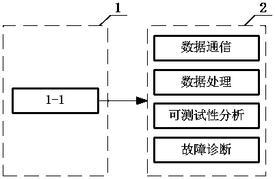
[0022] Specific implementation mode one: the following combination figure 1 This embodiment will be described. The flyback power supply with testability analysis and fault diagnosis functions described in this embodiment is composed of a flyback power supply module 1 and a host computer system 2, wherein:
[0023] The flyback power supply module 1 is a constant current source with an output current of 700mA selected from an LED drive power supply. There are a total of 14 key test nodes 1-1 in each part of the circuit.
[0024] The host computer system 2 is connected to the flyback power supply module 1, and is controlled by the host computer system 2 to complete the collection of voltage signals of the corresponding key test nodes 1-1.
specific Embodiment approach 2
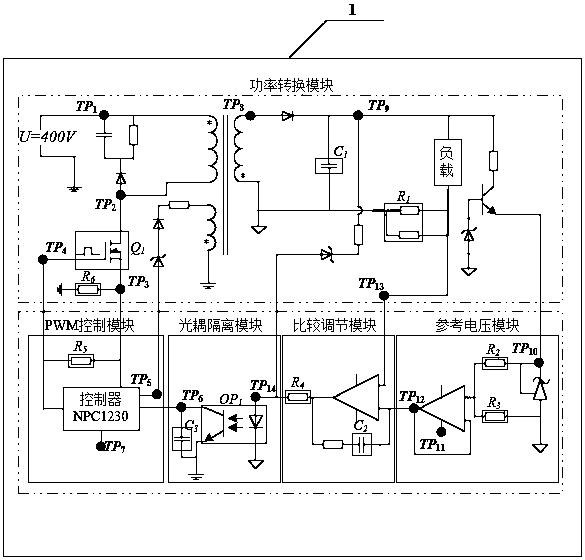
[0025] Specific implementation mode two: this implementation mode is a further description of specific implementation mode one, combined below figure 2 This embodiment will be described. The flyback power supply module 1 described in this embodiment includes 14 key test nodes 1-1 in total, including the input voltage point, output voltage point, feedback voltage point, optocoupler input voltage point, optocoupler output voltage of the flyback power supply point, reference voltage point, MOSFET gate voltage point, MOSFET source voltage point, MOSFET drain voltage point, etc. Such as figure 2 Shown, TP 1 400V input voltage, TP 2 is the drain voltage, TP 3 is the source voltage, TP 4 is the gate voltage, TP 5 is the auxiliary supply voltage, TP 6 is the optocoupler output voltage, TP 7 Output 15V voltage for NCP1230, TP 8 is the diode input voltage, TP 9 is the output voltage, TP 10 Supply voltage for TL431, TP 11 Supply voltage for op amp, TP 12 is the reference v...
specific Embodiment approach 3
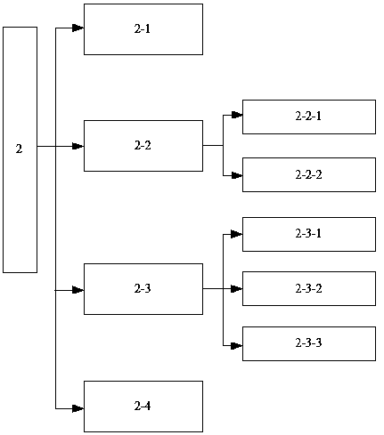
[0026] Specific implementation mode three: this implementation mode is a further description of specific implementation mode one, combined below image 3 This embodiment will be described. The upper computer system 2 described in this embodiment includes a data communication 2-1, a data processing interface 2-2, a testability analysis interface 2-3 and a fault diagnosis interface 2-4, wherein:
[0027] The data communication 2-1 is the communication between the host computer system 2 and the flyback power supply module 1, mainly including the host computer system 2 sending instructions to the chip STM32 in the power board to control its measurement of the voltage data of the test node Afterwards, the chip STM32 in the power board transmits the data to the upper computer system 2 again.
[0028] The data processing interface 2-2 is composed of a feature parameter selection 2-2-1 and a waveform display before and after processing 2-2-2. After the setting of selected characteri...
PUM
 Abstract
Description
Claims
Application Information
 - Generate Ideas
- Intellectual Property
- Life Sciences
- Materials
- Tech Scout
- Unparalleled Data Quality
- Higher Quality Content
- 60% Fewer Hallucinations
Browse by: Latest US Patents, China's latest patents, Technical Efficacy Thesaurus, Application Domain, Technology Topic, Popular Technical Reports.
© 2025 PatSnap. All rights reserved.Legal|Privacy policy|Modern Slavery Act Transparency Statement|Sitemap|About US| Contact US: help@patsnap.com